3-38
CCU-700A
CCU-700AP
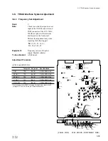
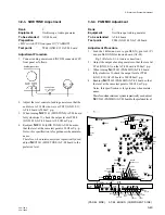
3-7-5. RX PROMPT VIDEO Level Adjustment
Rank
:
B
Note
:
When adjusting this step, the length of
triaxial cable is required less than 500 m.
Adjustment of BVP-700/700P must
be completed.
Equipment
:
Oscilloscope,
Video signal generator (10 STEP signal)
To be extended
:
DM-94 board
Preparation
• S4 (CCU
→
CAM/CAM
→
CCU)/
MD-83 board (BVP side)
→
“CAM
→
CCU”
• Remove the green harness of MPX filter from CN35
(PROMPT) connector on DM-97 board (BVP side).
And connect its harness to CN27 (PROMPT
REVERSE)/MB-430 board (BVP side).
• S5 (TX
←
→
RX)/
DM-94 board (CCU-700A/700AP)
→
“RX”
• S6 (TX
←
→
RX)/
DM-94 board (CCU-700A/700AP)
→
“RX”
• S1 (MODE AUTO/MAN)/
DM-94 board (CCU-700A/700AP)
→
“AUTO”
• PROMPT OUT/rear panel
→
Disconnect 75
Z
termination
• Feed the 10 STEP signal from the video signal generator
to PROMPTER connector (camera side panel).
Adjustment Procedure
• Adjust
1
RV23 (PROMPT LEVEL)/DM-94 board so
that the video level at pin D34 (GND: pin C34)/exten-
sion board is 2.00
±
0.05 V p-p.
Note
: After the adjustment, set the switches as follows.
• S4 (CCU
→
CAM/CAM
→
CCU) switch/
MD-83 board (BVP side)
→
“CCU
→
CAM”
• Return the green harness of MPX filter to CN35
(PROMPT) connector on DM-97 board (BVP side).
• S5 (TX
←
→
RX) switch/DM-94 board
→
“TX”
• S6 (TX
←
→
RX) switch/DM-94 board
→
“TX”
• Remove the BNC cable from the PROMPTER
connector/CCU rear panel.
3-7. PROMPT VIDEO Cable Compensation System Adjustment
-
12
-
5
+5
+12
DM
E15
E6
E9
TP18
TP12
TP24
TP23
E16
TP25
TP16
TP26
TP10
RV19
RV20
TP20
E11
CV1
*
TP21
RV21
CV3
CV2
LV2
RV22
LV3
E13
*
TP22
E10
RV8
RV7
RV6
TP9
RV24
RV3
TP6
RV11
RV16
RV18
RV15
RV14
RV13
TP15
E8
E12
TP14
RV5
RV2
RV4
TP8
TP7
TP4
TP1
E4
TP13
E7
E1
TP22
RV10
LV1
TP3
TP2
E2
TP5
TX
RX
S5
E5
ON
S4
RV1
TP21
RV23
E14
TP11
TP19
TP17
E3
RV12
RV17
RV9
S1
S2
Y GND
Y
B
-
Y
R
-
Y
R
-
Y
B
-
Y
ON
S3
Y AGC COUNT
S6
TX
RX
MAN
AUTO
CABLE
LENGTH
SUFFIX-12 ONLY
*
(PANEL SIDE) DM-94 BOARD (COMPONENT SIDE)
2.00+0.05 Vp-p
–


