3-47
CCU-700 A
CCU-700AP
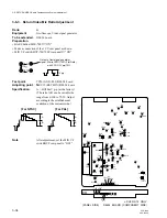
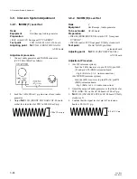
3-8-14. CHU TONE Adjustment
Rank
:
C
Equipment
:
Oscilloscope (DC mode)
To be extended
:
AT-88 board
Test point
:
TP7 (GND: E2)/AT-88 board
Adjusting point
:
1
RV101 (TONE TUNE)/
AT-88 board
Adjustment procedure
1.
1
RV101 (TONE TUNE)/
AT-88 board
→
Mechanical center
2.
Turn
1
RV101 (TONE TUNE)/AT-88 board slowly
clockwise
2
until the sine-wave waveform just
appears.
Measure the DC voltage “a”.
…
Fig-1
3.
Turn
1
RV101 (TONE TUNE)/AT-88 board slowly
counterclockwise
3
until the sine-wave waveform just
appears.
Measure the DC voltage “b”.
…
Fig-2
4.
Adjust
1
RV101 (TONE TUNE)/AT-88 board so that
DC level is half way between position “a” and
“b”.
…
Fig-3
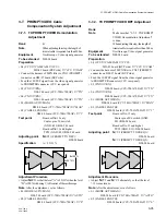
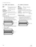
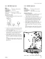
3-8-13. CHU DATA Demod. Adjustment
Rank
:
C
Note
:
The adjustment for BVP-700/700P
camera must be completed.
Perform the adjustment only when
replacing
1
LV101 (5.6 MHz TUNE)/
AT-88 board.
Equipment
:
Oscilloscope
To be extended
:
AT-88 board
Test point
:
TP6 (GND: E2)/AT-88 board
Adjusting point
:
1
LV101 (5.6 MHz TUNE)/
AT-88 board
Specification
:
–0.20
±
0.02 V dc
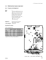
3-8. TRIAX Interface System Adjustment
E1000
TP1001
TP22
TP23
S1001
MODE1
S1002
MODE2
TP21
E2
E20
S2081
RV2382
TP47
TP48
E12
S2082 S2083
S2061
S2341
RV2301
RV2302
TP10
TP13
TP9
TP15
TP17
RV501
RV401
TP12
S301
RV201
RV301
LV1 LV21
TP1
TP2
TP7
RV101
RV81
LV81
RV61
LV61
RV41
LV41
TP5
TP4
TP3
TP6
T401
T501
TP16
TP14
TP11 TP8
LV101
TP45
TP44
E1
TP42
E11
TP46
S2491
ENG SELECT
S1004
S1003
S1005
S2301 S2062
TP43
TP40
E10
RV2342
RV2341
RV2451
RV2452
RV2491
RV2211
RV2212
RV2241
S2241
PROD SELECT
-
12
-
5
+5
+12
NORM
MIN
CH
-
1
NORM
MIN
CH
-
2 CLEAR
MIC LEVEL
CCU PAINT
REAR
INCOM MIC
DYNAMIC
CARBON
ENG
PRIVATE
PROD
PGM
MIX
INCOM
SELECT
SIDE
TONE
2W
LEVEL
2W
CANCEL
RTS
CANCEL
2W
LEVEL
2W
CANCEL
RTS
CANCEL
ENG
PROD
AT
S201
T301
T201
(PANEL SIDE) AT-88 BOARD (COMPONENT SIDE)
RV2310
(Fig-1)
Position “a”
Mechanical centert
(Fig-2)
Position “a”
Position “b”
(Fig-3)
Position “a”
Position “b”
A
A=B
B
center
0.20 ± 0.02 V
GND


