1
CCU-700A
CCU-700AP
Table of Contents
Manual Structure
Purpose of this manual .............................................................................................. 5
Contents ..................................................................................................................... 5
Relative manuals ....................................................................................................... 5
1. Installation
1-1.
Supplied Accessories .................................................................................. 1-1
1-1-1.
CCU-700A/700AP Supplied Accessories .................................. 1-1
1-1-2.
BKP-7312 Supplied Accessories ............................................... 1-1
1-2.
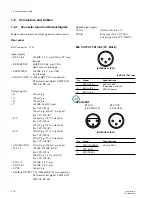
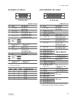
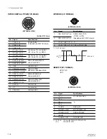
Connectors and Cables ................................................................................ 1-2
1-2-1.
Connector Input and Output Signals .......................................... 1-2
1-2-2.
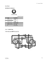
Cable Wiring .............................................................................. 1-5
1-2-3.
Connection Connector ................................................................ 1-6
1-3.
Installation ................................................................................................... 1-7
1-3-1.
Installation Conditions ............................................................... 1-7
1-3-2.
Outside Dimension ..................................................................... 1-7
1-3-3.
Installation of BKP-7312 ........................................................... 1-7
1-3-4.
How to Mount in 19-inch Rack .................................................. 1-9
1-4.
Function of Internal Switch ....................................................................... 1-12
1-5.
Coax Connector ......................................................................................... 1-18
1-6.
Peripheral Equipments and Accessories ................................................... 1-19
1-7.
Instance of System Configuration ............................................................. 1-20
2. Service Overview
2-1.
Replacement of Main Parts ......................................................................... 2-1
2-1-1.
Removal of Front Panel ............................................................. 2-1
2-1-2.
Removal of Rear Panel ............................................................... 2-1
2-1-3.
Disconnecting / Connecting of Flexible Card Wire ................... 2-2
2-1-4.
Installation of Rear Panel ........................................................... 2-2
2-1-5.
Replacement of TRIAX Connector ............................................ 2-2
2-1-6.
Replacement of Power Unit ....................................................... 2-3
2-1-7.
DC Fan Motor Replacement ...................................................... 2-4
2-2.
Note on Servicing ........................................................................................ 2-4
2-2-1.
Precaution of Replacement Parts ............................................... 2-4
2-2-2.
PROM IC ................................................................................... 2-4


