3-11
CCU-700A
CCU-700AP
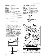
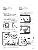
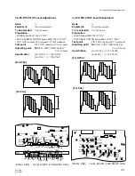
3-3-14. Burst Adjustment
Rank
:
B
Equipment
:
Vectorscope (INT REF mode)
To be extended
:
VA-156 board
Preparation
• BARS button/MSU-700
→
“ON”
• S1361 (I/V ON/OFF)/VA-156 board
→
“ON”
• S1362 (Q/U ON/OFF)/VA-156 board
→
“OFF”
Test point
:
VBS 1 OUT connector/CCU rear panel
(75
Z
terminated)
Adjustment Procedure
1.
Overlap the burst component to B-Y axis with PHASE
control on the vectorscope.
2.
Adjust the burst level properly with
1
RV1303 (BF
GAIN)/VA-156 board.
3.
Confirm that the burst level at VIDEO OUT is 40
±
2
IRE(for PAL:300
±
10 mV) using the waveform
monitor.
4.
Overlap both tips of the I (V) signal component to I
(V) axis with
1
RV1304 (BF PHASE)/VA-156 board.
Note
: After the adjustment, set as follows.
• S1362 (Q/U ON/OFF)/VA-156 board
→
“ON”
• Re-check “3-3-13. Color Vector Adjustment”.
[For NTSC]
[For PAL]
R
M
G
C
Y
G
Y
L
B
R
M
G
Y
L
B
C
Y
G
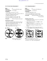
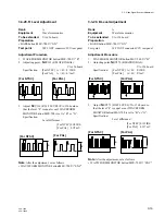
3-3-13. Color Vector Adjustment
Rank
:
B
Equipment
:
Vectorscope (EXT REF mode)
To be extended
:
VA-156 board
Preparation
• GAIN switch/Vectorscope
→
75% CAL
• Adjust the PHASE control on the vectorscope so that the
burst spot is overlapped to the 75% axis.
• BARS button/MSU-700
→
“ON”
• S1361 (I/V ON/OFF)/VA-156 board
→
“ON”
• S1362 (Q/U ON/OFF)/VA-156 board
→
“ON”
Test point
:
VBS 1 OUT connector/rear panel
Adjustment Procedure
• Adjust the following controls aiternately so that each
beam spot is located inside the reference frame “
4
”.
1
LV1361(SC QUAD)/VA-156 board
1
RV1364(CHROMA LEVEL)/VA-156 board
1
RV1361(Q/U BAL)/VA-156 board
Note
:
After the adjustment, carry out
“3-3-14. Burst Adjustment” .
3-3. Video Signal System Adjustment
R
M
G
B
C
Y
G
Y
L
R
M
G
C
Y
G
Y
L
B
[For NTSC]
[For PAL]


