163/238
Building Technologies
Modular Heating Controller RMH760B
CE1P3133en
HVAC Products
10 DHW heating
05.02.2007
2. Increase Tv in steps of 2 to 5 seconds while the load is at its maximum.
If this is not sufficient:
3.
Increase Tn in steps of 10 to 20 seconds while the load is at its maximum.
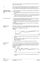
To check the control, the start is made again with the preset control parameters, but
this time under minimum load conditions.
•
Minimum load means the lowest velocity of flow on the DHW side (e.g. circulation
load) at the reduced setpoint
•
For the control system, the load under frost protection conditions is only of minor
importance; for this reason, the frost protection setpoint should not be selected
•
Under these minimum load conditions, the controller should maintain the setpoint for
a certain period of time. Then, increase or decrease the setpoint by 5…10 %
If the correcting action does not produce the desired result, control parameters Xp, Tv
and Tn should be readjusted this time under minimum load conditions according to the
above paragraphs “Control action is too slow” and “Control action is too fast”. When
readjusting the parameters, “…while the load is at its maximum“ should be replaced
here by “… when the load is at its minimum”.
10.5.2 Requirements for the plant
The correct location of the secondary flow sensor is very important! If no flow switch is
used, it must be made certain that the flow sensor immerses into the heat exchanger.
If the flow sensor is not correctly sited,
there is a risk of excessive heat exchanger
temperatures
.
Apart from certain hydraulic prerequisites, good control performance can only be
achieved under the following conditions:
1. Use of a fast-acting actuator having a running time of
≤
15 seconds
2. The time constant of the secondary flow temperature sensor as an immersion sensor
should be about 2 seconds
3. The secondary flow temperature sensor should be located about 100 to 200 mm
outside the heat exchanger (item 4. must be satisfied; otherwise, refer to items 1.
and 2.)
4. Use of a flow switch
5. The circulation pipe joins the DHW supply line by the heat exchanger
10.5.3 Flow switch
When using a flow switch, the controller can detect start and end of DHW consumption
at an early stage, enabling it to respond accordingly. This gives the controller a lead
over control systems which only use a flow temperature sensor, also preventing exces-
sive water temperatures.
313
3S
81
Use of a flow switch proves particularly advantageous in the case of smaller plants,
such as single-family homes, but improves plant performance in all other cases as well.
Fault status supervision is not possible since short-circuits and open-circuits are permit-
ted states.
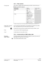
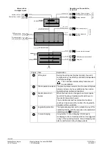
The flow switch is to be activated by assigning a terminal:
Checking the control
function at minimum
load
Notes on minimum load
Extra configuration

