


2 Functions
62
7ST6 Manual
E50417-G1176-C251-A3
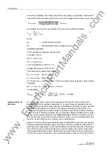
secondary quantities, the values derived from the grading coordination chart must be
converted to the secondary side of the current and voltage transformers. In general:
Accordingly, the reach for any distance zone can be specified as follows:
where:
N
CT
= Current transformer ratio
N
VT
= Transformation ratio of voltage transformer
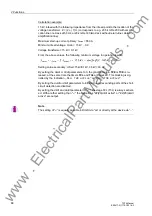
Calculation example:
15 kV overhead contact line with the data:
s (length) = 35 km
R1/s = 0.19
Ω
/km
X1/s = 0.42
Ω
/km
Current transformers 1000 A / 1 A
Voltage transformers 15 kV/0.1 kV
The following line data is calculated:
R
L
= 0.19
Ω
/km · 35 km = 6.65
Ω
X
L
= 0.42
Ω
/km · 35 km = 14.70
Ω
For the first zone, a setting of 85 % of the line length should be applied, which results
in primary:
X1
Prim
= 0.85 · X
L
= 0.85 · 14.70
Ω
= 12.49
Ω
or secondary:
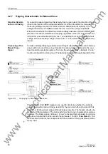
Determination of
Direction
An impedance vector is also used to determine the direction of the short-circuit.
Usually similar to the distance calculation, Z
L
is used. However, depending on the
"quality" of the measured values, different computation techniques are used. Immedi-
ately after fault inception, the short-circuit voltage is disturbed by transients. The
voltage memorized prior to fault inception is therefore used in this situation. If there is
neither a current measured voltage nor a memorised voltage available which is suffi-
cient for measuring the direction, the "
forward
reverse
" direction is selected. In prac-
tice this can only occur when the circuit breaker closes onto a de-energised line, and
there is a fault on this line (e.g. closing onto an earthed line).
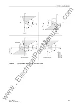
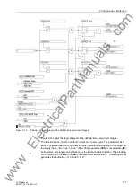
Figure 2-12 shows the theoretical steady-state characteristic. In practice, the position
of the directional characteristic when using the memorized voltage is dependent on
both the source impedance and the load transferred across the line prior to fault incep-
tion. If the direction is determined from the current voltage, the position of the direc-
tional characteristic with double infeed and a high fault resistance is also dependent
on both the source impedance and the load transferred across the line prior to fault
www
. ElectricalPartManuals
. com
Содержание SIPROTEC 7ST6
Страница 14: ...Contents 14 7ST6 Manual E50417 G1176 C251 A3 w w w E l e c t r i c a l P a r t M a n u a l s c o m ...
Страница 24: ...1 Introduction 24 7ST6 Manual E50417 G1176 C251 A3 w w w E l e c t r i c a l P a r t M a n u a l s c o m ...
Страница 254: ...3 Mounting and Commissioning 254 7ST6 Manual E50417 G1176 C251 A3 w w w E l e c t r i c a l P a r t M a n u a l s c o m ...
Страница 288: ...4 Technical Data 288 7ST6 Manual E50417 G1176 C251 A3 w w w E l e c t r i c a l P a r t M a n u a l s c o m ...
Страница 340: ...A Appendix 340 7ST6 Manual E50417 G1176 C251 A3 w w w E l e c t r i c a l P a r t M a n u a l s c o m ...
Страница 342: ...Literature 342 7ST6 Manual E50417 G1176 C251 A3 w w w E l e c t r i c a l P a r t M a n u a l s c o m ...
Страница 354: ...Index 354 7ST6 Manual E50417 G1176 C251 A3 w w w E l e c t r i c a l P a r t M a n u a l s c o m ...
Страница 355: ...Index 355 7ST6 Manual E50417 G1176 C251 A3 w w w E l e c t r i c a l P a r t M a n u a l s c o m ...
Страница 356: ...Index 356 7ST6 Manual E50417 G1176 C251 A3 w w w E l e c t r i c a l P a r t M a n u a l s c o m ...