


3 Mounting and Commissioning
214
7ST6 Manual
E50417-G1176-C251-A3
• Remove the caps on the front cover of the device and withdraw the then accessible
screws.
• Remove the front cover and tilt it to the side. With device versions with a detached
operator panel it is possible to remove the front cover of the device right after having
unscrewed all screws.
Work on the Plug
Connectors
Caution!
Mind electrostatic discharges:
Non–observance can result in minor personal injury or material damage.
When handling plug connectors, eliminate electrostatic discharges by first touching an
earthed metal surface.
Do not plug in or pull off interface terminals under voltage!
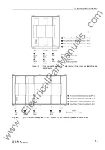
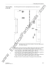
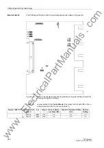
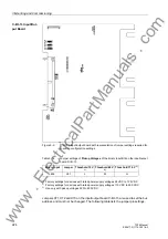
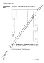
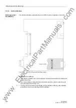
The assembly of the boards for the housing size
1
/
2
is shown in Figure 3-3 and for the
housing size
1
/
1
in Figure 3-4.
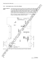
• Disconnect the plug connector of the ribbon cable between the front cover and the
processor board C-CPU-2 at the front cover side. To do this, spread the latches on
the upper and lower end of the plug connector to release the plug connector of the
ribbon cable. This action does not apply to the device version with detached oper-
ator panel. However, on the central processor unit C–CPU-2 (No. 1) the 7-pole plug
connector X16 behind the D-subminiature connector and the plug connector of the
ribbon cable (connected to the 68-pole plug connector on the rear side) must be re-
moved.
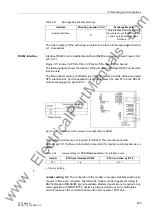
• Disconnect the ribbon cables between the processor board C-CPU-2 (No. 1) and
the input/output boards I/O (No. 2 to No. 6, depending on the ordered variant).
• Remove the modules and place them on a surface suitable for electrostatically sen-
sitive modules (ESD).
• Check the jumpers according to Figures 3-5 to 3-10, 3-13, 3-14 and the following
information. Change or remove the jumpers if necessary.
www
. ElectricalPartManuals
. com
Содержание SIPROTEC 7ST6
Страница 14: ...Contents 14 7ST6 Manual E50417 G1176 C251 A3 w w w E l e c t r i c a l P a r t M a n u a l s c o m ...
Страница 24: ...1 Introduction 24 7ST6 Manual E50417 G1176 C251 A3 w w w E l e c t r i c a l P a r t M a n u a l s c o m ...
Страница 254: ...3 Mounting and Commissioning 254 7ST6 Manual E50417 G1176 C251 A3 w w w E l e c t r i c a l P a r t M a n u a l s c o m ...
Страница 288: ...4 Technical Data 288 7ST6 Manual E50417 G1176 C251 A3 w w w E l e c t r i c a l P a r t M a n u a l s c o m ...
Страница 340: ...A Appendix 340 7ST6 Manual E50417 G1176 C251 A3 w w w E l e c t r i c a l P a r t M a n u a l s c o m ...
Страница 342: ...Literature 342 7ST6 Manual E50417 G1176 C251 A3 w w w E l e c t r i c a l P a r t M a n u a l s c o m ...
Страница 354: ...Index 354 7ST6 Manual E50417 G1176 C251 A3 w w w E l e c t r i c a l P a r t M a n u a l s c o m ...
Страница 355: ...Index 355 7ST6 Manual E50417 G1176 C251 A3 w w w E l e c t r i c a l P a r t M a n u a l s c o m ...
Страница 356: ...Index 356 7ST6 Manual E50417 G1176 C251 A3 w w w E l e c t r i c a l P a r t M a n u a l s c o m ...