


3.3 Commissioning
249
7ST6 Manual
E50417-G1176-C251-A3
3.3.7
Direction Check with Load Current
Load Current
≥
[10% I N ]
The correct connection of the current and voltage transformers is tested via the pro-
tected line using the load current. For this purpose, connect the line. The load current
the line carries must be at least 0.1 · I
N
. The load current should be in-phase or lagging
the voltage (resistive or resistive-inductive load). The direction of the load current must
be known. If there is a doubt, network or ring loops should be opened. The line
remains energized during the test.
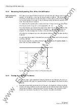
The direction can be derived directly from the operational measured values. Initially
the correlation of the measured load direction with the actual direction of load flow is
checked. In this case the normal situation is assumed, where the forward direction
(measuring direction) extends from the busbar towards the line (see the following fig-
ure).
P
positive, if active power flows into the line,
P
negative, if active power flows towards the busbar,
Q
positive, if reactive power flows into the line,
Q
negative, if reactive power flows toward the busbar.
Figure 3-23
Apparent Load Power
The power measurement provides an initial indication as to whether the measured
values have the correct polarity. If both the active power as well as the reactive power
have the wrong sign, the polarity in address
201
CT Starpoint
must be checked
and rectified.
However, power metering itself is not able to detect all connection errors. Therefore,
the impedance of the phase loop is read out as well. This impedance can also be
found as primary and secondary quantity in the operational measured values.
In addition, the following applies for the impedance when the load is in the first quad-
rant:
R
,
X
both positive, when power flows into the line,
R
,
X
both negative, when power flows towards the busbar.
In this case the normal situation is assumed, where the forward direction (measuring
direction) extends from the busbar towards the line. In the case of capacitive load, the
X-component may have the opposite sign.
Finally, switch off the protected power line.
www
. ElectricalPartManuals
. com
Содержание SIPROTEC 7ST6
Страница 14: ...Contents 14 7ST6 Manual E50417 G1176 C251 A3 w w w E l e c t r i c a l P a r t M a n u a l s c o m ...
Страница 24: ...1 Introduction 24 7ST6 Manual E50417 G1176 C251 A3 w w w E l e c t r i c a l P a r t M a n u a l s c o m ...
Страница 254: ...3 Mounting and Commissioning 254 7ST6 Manual E50417 G1176 C251 A3 w w w E l e c t r i c a l P a r t M a n u a l s c o m ...
Страница 288: ...4 Technical Data 288 7ST6 Manual E50417 G1176 C251 A3 w w w E l e c t r i c a l P a r t M a n u a l s c o m ...
Страница 340: ...A Appendix 340 7ST6 Manual E50417 G1176 C251 A3 w w w E l e c t r i c a l P a r t M a n u a l s c o m ...
Страница 342: ...Literature 342 7ST6 Manual E50417 G1176 C251 A3 w w w E l e c t r i c a l P a r t M a n u a l s c o m ...
Страница 354: ...Index 354 7ST6 Manual E50417 G1176 C251 A3 w w w E l e c t r i c a l P a r t M a n u a l s c o m ...
Страница 355: ...Index 355 7ST6 Manual E50417 G1176 C251 A3 w w w E l e c t r i c a l P a r t M a n u a l s c o m ...
Страница 356: ...Index 356 7ST6 Manual E50417 G1176 C251 A3 w w w E l e c t r i c a l P a r t M a n u a l s c o m ...