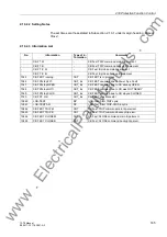


2.19 Auxiliary Functions
187
7ST6 Manual
E50417-G1176-C251-A3
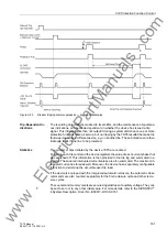
In all other respects, the properties of the fast binary outputs are the same as the
general properties of the binary outputs described above.
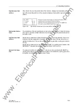
Information on the
Integrated Display
(LCD) or to a Per-
sonal Computer
Events and conditions can be read out on the display on the front cover of the relay.
Using the front PC interface or the rear service interface, for instance, a personal com-
puter can be connected, to which the information can be sent.
In the quiescent state, i.e. as long as no system fault is present, the LCD can display
selectable operational information (overview of the operational measured values) (de-
fault display). In the event of a system fault, information regarding the fault, the so-
called spontaneous indications, are displayed instead. After the fault indications have
been acknowledged, the quiescent data are shown again. Acknowledgement can be
performed by pressing the LED buttons on the front panel (see above).
The device in addition has several event buffers for operational indications, fault indi-
cations, switching statistics, etc., which are saved against loss of auxiliary supply by
means of a battery buffer. These indications can be displayed on the LCD at any time
by selection using the keypad or transferred to a personal computer via the serial
service or PC interface. The retrieval of indications during operation is extensively de-
scribed in the SIPROTEC
®
4 System Description, Order No. E50417-H1176-C151).
After a fault on the system, for example, important information about the progression
of the fault can be retrieved, such as the pickup of a protective element or the initiation
of a trip signal. The start of the fault is time stamped with the absolute time of the in-
ternal system clock. The progress of the disturbance is output with a relative time re-
ferred to the instant of fault detection, so that the duration of the fault until tripping and
up to reset of the trip command can be ascertained. The resolution of the time infor-
mation is 1 ms.
With a PC and the DIGSI
®
protection data processing software it is also possible to
retrieve and display the events with the convenience of visualization on a monitor and
a menu-guided dialog. The data may either be printed or stored for evaluation at a later
time and place.
The protection device stores the indications of the last eight system faults; in the event
of a ninth fault, the oldest is erased.
A system fault starts with the recognition of the fault by the fault detection of any pro-
tection function and ends with the reset of the fault detection of the last protection func-
tion or after the expiry of the auto-reclose reclaim time, so that several unsuccessful
auto-reclose cycles are also stored cohesively. Accordingly a system fault may contain
several individual fault events (from fault detection up to reset of fault detection).
Information to a
Control Centre
If the device has a serial system interface, stored information may additionally be
transferred via this interface to a centralized control and storage device. Transmission
is possible using different transmission protocols.
You may test whether the indications are transmitted correctly with DIGSI
®
.
Also the information transmitted to the control centre can be influenced during opera-
tion or tests. The IEC 60870-5-103 protocol allows to identify all indications and mea-
sured values transferred to the central control system with an added indication „test
mode“ while the device is being tested on site (test mode). This identification prevents
the indications from being incorrectly interpreted as resulting from an actual power
system disturbance or event. Alternatively, you may disable the transmission of indi-
cations to the system interface during tests („Transmission block“).
www
. ElectricalPartManuals
. com
Содержание SIPROTEC 7ST6
Страница 14: ...Contents 14 7ST6 Manual E50417 G1176 C251 A3 w w w E l e c t r i c a l P a r t M a n u a l s c o m ...
Страница 24: ...1 Introduction 24 7ST6 Manual E50417 G1176 C251 A3 w w w E l e c t r i c a l P a r t M a n u a l s c o m ...
Страница 254: ...3 Mounting and Commissioning 254 7ST6 Manual E50417 G1176 C251 A3 w w w E l e c t r i c a l P a r t M a n u a l s c o m ...
Страница 288: ...4 Technical Data 288 7ST6 Manual E50417 G1176 C251 A3 w w w E l e c t r i c a l P a r t M a n u a l s c o m ...
Страница 340: ...A Appendix 340 7ST6 Manual E50417 G1176 C251 A3 w w w E l e c t r i c a l P a r t M a n u a l s c o m ...
Страница 342: ...Literature 342 7ST6 Manual E50417 G1176 C251 A3 w w w E l e c t r i c a l P a r t M a n u a l s c o m ...
Страница 354: ...Index 354 7ST6 Manual E50417 G1176 C251 A3 w w w E l e c t r i c a l P a r t M a n u a l s c o m ...
Страница 355: ...Index 355 7ST6 Manual E50417 G1176 C251 A3 w w w E l e c t r i c a l P a r t M a n u a l s c o m ...
Страница 356: ...Index 356 7ST6 Manual E50417 G1176 C251 A3 w w w E l e c t r i c a l P a r t M a n u a l s c o m ...