
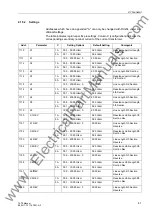


2 Functions
34
7ST6 Manual
E50417-G1176-C251-A3
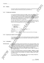
In auto-transformer systems, the protection functions can evaluate either
• The summation current of the overhead contact line current and the negative feeder
current, or
• The overhead contact line current
In the parameter
CURRENT I1, I2
(address
213
) you specify which current will be
fed to the protection functions for evaluation. If you want the summation current to be
processed by the protection functions, set address
213
to
Sum I1, I2
. The vectors
of the overhead contact line current and the negative feeder current are added.
Note
If at address
213
the parameter
CURRENT I1, I2
is set to
Sum I1, I2
, the setting
of jumper X600 on the C-I/O 13 board must be changed for the summation! The
default setting of this jumper on delivery is „without summation“!
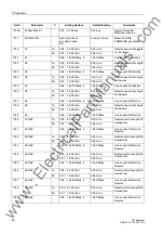
Transformer Data
for Defrosting
In address
211
IX CT STARPOINT
the polarity of the current transformers (defrosting
current) must be stated. This setting determines the measuring direction of the device
(forwards = line direction).
At address
212
IX CT PRIMARY
you set the primary rated CT current (defrosting cur-
rent).
Transformer Data
for Synchro-check
If in the Functional Scope of the device the synchro-check function =
Enabled
(ad-
dress
135
) has been configured, the following parameters must be set in the
P.System Data 1
:
At address
215
Uline/Uref
you set the matching factor for the different transform-
ers of the overhead contact line Vline and of the reference voltage Vref.
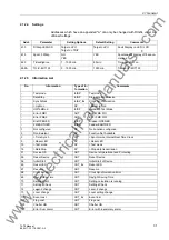
System Data
The permissible rated frequencies depend on the device variant: 16.7 Hz or 25 to 60
Hz. In the second variant, the rated frequency can be changed at address
230
Rated
Frequency
; options are 25 Hz, 50 Hz and 60 Hz.
The 7ST6 device supports several line sections with different reactance per unit length
characteristics for the conversion of a fault impedance into a fault distance. The
number of line sections with different reactance per unit length characteristics can be
set in address
234
No. SECTIONS
and
235
No.SECTIONS REV
. The settings that
you apply here determine the setting parameters for the reactance per unit length
characteristics that will be shown in the
P.System Data 2
in the setting sheet .
Address
236
Distance Unit
allows to determine the unit of length (
km
or
Miles
)
for the fault location indications. This parameter is not relevant if no fault detection is
available. Changing the length unit will not result in an automatic conversion between
the systems. Such conversions must be entered at the appropriate addresses.
www
. ElectricalPartManuals
. com
Содержание SIPROTEC 7ST6
Страница 14: ...Contents 14 7ST6 Manual E50417 G1176 C251 A3 w w w E l e c t r i c a l P a r t M a n u a l s c o m ...
Страница 24: ...1 Introduction 24 7ST6 Manual E50417 G1176 C251 A3 w w w E l e c t r i c a l P a r t M a n u a l s c o m ...
Страница 254: ...3 Mounting and Commissioning 254 7ST6 Manual E50417 G1176 C251 A3 w w w E l e c t r i c a l P a r t M a n u a l s c o m ...
Страница 288: ...4 Technical Data 288 7ST6 Manual E50417 G1176 C251 A3 w w w E l e c t r i c a l P a r t M a n u a l s c o m ...
Страница 340: ...A Appendix 340 7ST6 Manual E50417 G1176 C251 A3 w w w E l e c t r i c a l P a r t M a n u a l s c o m ...
Страница 342: ...Literature 342 7ST6 Manual E50417 G1176 C251 A3 w w w E l e c t r i c a l P a r t M a n u a l s c o m ...
Страница 354: ...Index 354 7ST6 Manual E50417 G1176 C251 A3 w w w E l e c t r i c a l P a r t M a n u a l s c o m ...
Страница 355: ...Index 355 7ST6 Manual E50417 G1176 C251 A3 w w w E l e c t r i c a l P a r t M a n u a l s c o m ...
Страница 356: ...Index 356 7ST6 Manual E50417 G1176 C251 A3 w w w E l e c t r i c a l P a r t M a n u a l s c o m ...