

3 Mounting and Commissioning
218
7ST6 Manual
E50417-G1176-C251-A3
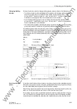
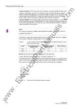
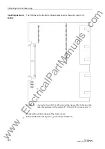
Jumper setting 2-3:
The connection to the modem is usually established with a star
coupler or fibre-optic converter. Therefore the modem control signals according to
RS232 standard DIN 66020 are not available. Modem signals are not required since
communication to SIPROTEC
®
4 devices is always carried out in the half duplex
mode. Please use the connection cable with order number 7XV5100-4.
Jumper setting 1-2
: This setting makes the modem signals available, i. e. for a direct
RS232 connection between the SIPROTEC
®
4 device and the modem this setting can
be selected optionally. We recommend to use a standard RS232 modem connection
cable (converter 9-pin to 25-pin).
Note
For a direct connection to DIGSI
®
with the RS232 interface, jumper X111 must be
plugged in position 2-3.
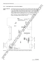
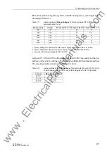
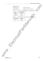
If there are no external matching resistors in the system, the last devices on a RS485
bus must be configured using jumpers X103 and X104.
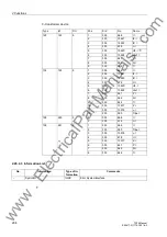
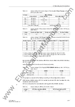
Table 3-7
Jumper settings of the
Terminating Resistors
of the RS485 interface on the C-
CPU-2 processor board
Note
: Both jumpers must always be plugged in the same way!
Jumper X90 has currently no function. The factory setting is 1-2.
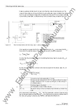
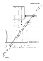
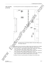
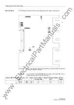
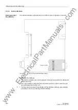
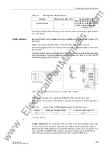
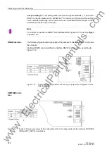
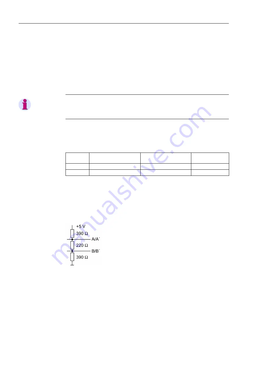
Terminating resistors can also be implemented outside the device (e.g. on the terminal
block). In this case, the matching resistors located on the RS485 or PROFIBUS inter-
face module or directly on the PCB of the C-CPU-2 board must be disabled.
Figure 3-6
Termination of the RS485 interface (external)
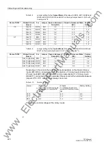
Jumper
Terminating Resistor
Switched ON
Terminating Resistor
Switched OFF
Factory Setting
X103
2-3
1-2
1-2
X104
2-3
1-2
1-2
www
. ElectricalPartManuals
. com
Содержание SIPROTEC 7ST6
Страница 14: ...Contents 14 7ST6 Manual E50417 G1176 C251 A3 w w w E l e c t r i c a l P a r t M a n u a l s c o m ...
Страница 24: ...1 Introduction 24 7ST6 Manual E50417 G1176 C251 A3 w w w E l e c t r i c a l P a r t M a n u a l s c o m ...
Страница 254: ...3 Mounting and Commissioning 254 7ST6 Manual E50417 G1176 C251 A3 w w w E l e c t r i c a l P a r t M a n u a l s c o m ...
Страница 288: ...4 Technical Data 288 7ST6 Manual E50417 G1176 C251 A3 w w w E l e c t r i c a l P a r t M a n u a l s c o m ...
Страница 340: ...A Appendix 340 7ST6 Manual E50417 G1176 C251 A3 w w w E l e c t r i c a l P a r t M a n u a l s c o m ...
Страница 342: ...Literature 342 7ST6 Manual E50417 G1176 C251 A3 w w w E l e c t r i c a l P a r t M a n u a l s c o m ...
Страница 354: ...Index 354 7ST6 Manual E50417 G1176 C251 A3 w w w E l e c t r i c a l P a r t M a n u a l s c o m ...
Страница 355: ...Index 355 7ST6 Manual E50417 G1176 C251 A3 w w w E l e c t r i c a l P a r t M a n u a l s c o m ...
Страница 356: ...Index 356 7ST6 Manual E50417 G1176 C251 A3 w w w E l e c t r i c a l P a r t M a n u a l s c o m ...