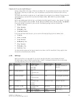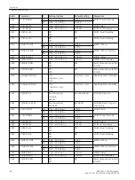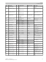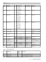
51-B PICKUP
,
67-TOC PICKUP
address 2633
51N-B PICKUP
,
67N-TOC PICKUP
address 2638
The setting of the current pickup value is basically determined by the maximum operational current. Pickup
due to overload must be excluded as the device operates as short-circuit protection in this mode with corre-
spondingly short command times and not as overload protection. A pickup value setting of about 10% is
recommended for line protection, and a setting of about 20% of the expected peak load is recommended for
transformers and motors.
The ground current elements detect the smallest anticipated ground fault current.
For very long lines with small source impedance or on applications with large reactances (e.g. series reactors),
the 50-2 elements can also be used for current grading. In this case, they must be set such that they do not
pickup reliably on a short circuit at the line end.
For the inverse time elements a safety margin between pickup value and setting value has already been imple-
mented. Pick up only occurs at a current which is approximately 10% above the set value. Please bear this in
mind when specifying the setting values of the inverse time elements.
If an element is not required, set the pickup value to ∞.
Time Delays
The time delays are set specifically for each element:
50-B2 DELAY
,
67-B2 DELAY
address 2624
50N-B2 DELAY
,
67N-B2 DELAY
address 2627
50-B1 DELAY
,
67-B1 DELAY
address 2614
50N-B1 DELAY
,
67N-B1 DELAY
address 2617
51-B TD IEC
,
67-TOC TD IEC
address 2634 (IEC characteristic)
51N-B TD IEC
,
67N-TOC TD IEC
address 2639 (IEC characteristic)
51-B TD ANSI
,
67-TOC TD ANSI
address 2635 (ANSI characteristic)
51N-B TD ANSI
,
67N-TOC TD ANSI
address 2640 (ANSI characteristic)
They are determined by the time grading chart created for the power system. If used as emergency overcur-
rent protection, shorter tripping times are advisable as this function is only activated in the case of the loss of
the local measuring voltage.
The times for the ground current elements can be set shorter, according to a separate time grading chart for
ground currents.
You can set additional time delays for definite-time elements with IEC characteristic.
51-B AddT-DELAY
,
67-TOC AddTDel.
address2636
51N-B AddTdelay
,
67N-TOC AddTDel
address 2641
Instantaneous Tripping via Binary Input
Binary input
>5X-B InstTRIP
allows you to bypass the time delays. The binary input applies to all elements
collectively.
You can specify for each element whether instantaneous tripping takes effect. The setting applies collectively
to the corresponding phase and ground element.
50-1, 3I0>
address 2628
50-2, 3I0>>
address 2618
50N, 3I0p
address 2644
The following settings are possible:
•
If set to
YES
, the element trips instantaneously when the binary input is activated.
•
If set to
NO
, the set time delays take effect.
Functions
2.4 Backup overcurrent
84
SIPROTEC 4, 7SD80, Manual
E50417-G1100-C474-A2, Edition 02.2018
Содержание SIPROTEC 4 7SD80
Страница 8: ...8 SIPROTEC 4 7SD80 Manual E50417 G1100 C474 A2 Edition 02 2018 ...
Страница 10: ...10 SIPROTEC 4 7SD80 Manual E50417 G1100 C474 A2 Edition 02 2018 ...
Страница 18: ...18 SIPROTEC 4 7SD80 Manual E50417 G1100 C474 A2 Edition 02 2018 ...
Страница 248: ...248 SIPROTEC 4 7SD80 Manual E50417 G1100 C474 A2 Edition 02 2018 ...
Страница 298: ...298 SIPROTEC 4 7SD80 Manual E50417 G1100 C474 A2 Edition 02 2018 ...
Страница 312: ...312 SIPROTEC 4 7SD80 Manual E50417 G1100 C474 A2 Edition 02 2018 ...
Страница 322: ...322 SIPROTEC 4 7SD80 Manual E50417 G1100 C474 A2 Edition 02 2018 ...
Страница 400: ...400 SIPROTEC 4 7SD80 Manual E50417 G1100 C474 A2 Edition 02 2018 ...
Страница 402: ...402 SIPROTEC 4 7SD80 Manual E50417 G1100 C474 A2 Edition 02 2018 ...

