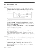


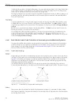
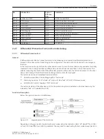


Determination of the Phase Affected by the Ground Fault
Following pickup caused by the displacement voltage, the phase affected by the ground fault is determined
first. To do this, the individual phase-to-ground voltages are measured. If the voltage magnitude for any given
phase is below the setting value V
min
, that phase is detected as the ground faulted phase as long as the
remaining phase-to-ground voltages are simultaneously above the setting value V
max
.
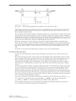
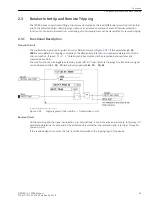
Sensitive Ground Fault Direction Determination
The direction of the ground fault can be determined from the direction of the ground fault current in relation
to the displacement voltage. The only restriction is that the active or reactive current components must be
available with sufficient magnitude at the point of measurement.
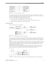
In networks with isolated starpoint, the ground fault current flows as capacitive current from the healthy lines
via the measuring point to the point of ground fault. For the determination of the direction the capacitive
reactive power is most relevant.
In networks with arc suppression coils, the Petersen coil superimposes a corresponding inductive current on
the capacitive ground fault current when a ground fault occurs, so that the capacitive current at the point of
fault is compensated. Depending on the measuring point in the system the resultant measured current may be
inductive or capacitive. Therefore, the reactive current is not suited for direction determination of the ground
current. In this case, only the ohmic (active) residual current which results from the losses of the Petersen coil
can be used for direction determination. This residual ground fault residual current is only about some per
cent of the capacitive ground fault current.
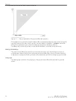
The active and reactive component of the power is decisive for the ground fault protection pickup.
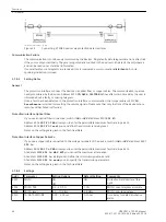
A fault in forward direction must be detected at both ends of the protected object for the ground fault differ-
ential protection to pick up.
In case of a single feeder, the residual current per watt at the opposite end of the infeed can be so weak that it
is impossible to determine the direction at that end. In this case, the amplitudes of the active currents of the
two ends are additionally compared to initiate pickup and localize the ground fault.
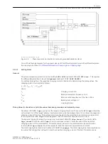
The amplitude of the active current (resonant-grounded system) and the reactive current (for isolated star-
point) are included in the fault record. The local wattmetric ground current or reactive current is recorded as
Ι
ee1, the wattmetric ground current or the reactive current of the opposite end as
Ι
ee2.
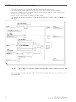
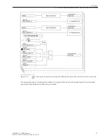
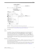
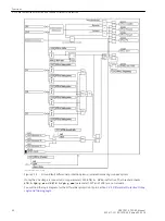
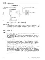
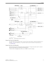
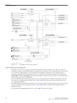
Pickup Logic
The following figure shows the pickup logic of the ground fault differential protection resonant-grounded or
isolated systems.
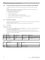
Functions
2.2 Phase Comparison Protection and Ground Differential Protection
SIPROTEC 4, 7SD80, Manual
59
E50417-G1100-C474-A2, Edition 02.2018
Содержание SIPROTEC 4 7SD80
Страница 8: ...8 SIPROTEC 4 7SD80 Manual E50417 G1100 C474 A2 Edition 02 2018 ...
Страница 10: ...10 SIPROTEC 4 7SD80 Manual E50417 G1100 C474 A2 Edition 02 2018 ...
Страница 18: ...18 SIPROTEC 4 7SD80 Manual E50417 G1100 C474 A2 Edition 02 2018 ...
Страница 248: ...248 SIPROTEC 4 7SD80 Manual E50417 G1100 C474 A2 Edition 02 2018 ...
Страница 298: ...298 SIPROTEC 4 7SD80 Manual E50417 G1100 C474 A2 Edition 02 2018 ...
Страница 312: ...312 SIPROTEC 4 7SD80 Manual E50417 G1100 C474 A2 Edition 02 2018 ...
Страница 322: ...322 SIPROTEC 4 7SD80 Manual E50417 G1100 C474 A2 Edition 02 2018 ...
Страница 400: ...400 SIPROTEC 4 7SD80 Manual E50417 G1100 C474 A2 Edition 02 2018 ...
Страница 402: ...402 SIPROTEC 4 7SD80 Manual E50417 G1100 C474 A2 Edition 02 2018 ...


