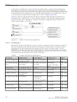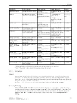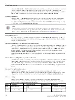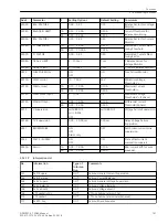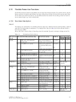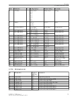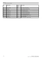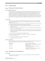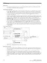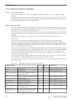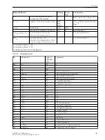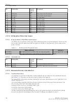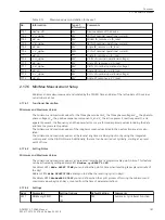
Parameter
OPERRAT. MODE
=
3-phase
Positive seq.
,
Negative seq.
,
Zero sequence
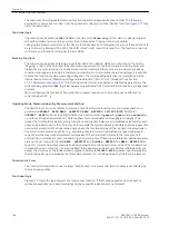
In order to realize certain applications, the positive sequence system or negative
sequence system can be configured as measurement procedure. Examples are:
- I2 (tripping monitoring system)
- U2 (voltage asymmetry)
Via the selection zero sequence system, additional zero sequence current or zero
sequence voltage functions can be realized that operate independent of the ground varia-
bles IN and VN, which are measured directly via transformers.
Important: The voltage threshold is always parameterized according to the definition of
the balanced components independently of parameter
VOLTAGE SYSTEM
.
Parameter
MEAS. QUANTITY
=
Current
Parameter
MEAS. METHOD
Ratio I2/I1
The ratio of the negative-sequence current to the positive-sequence current is evaluated.
Please note that the function only operates if
Ι
2 or
Ι
1 has exceeded the threshold value
0.1 ·
Ι
N
.
Parameter
MEAS. QUANTITY
=
Voltage
Parameter
VOLTAGE
SYSTEM
Phase-Phase
Phase-Ground
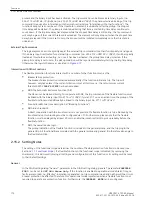
You can select whether a three-phase operating voltage function must evaluate the
phase-to-ground or phase-to-phase voltages.
When selecting phase-to-phase, these variables are derived from the phase-to-ground
voltages. The selection is, for example, important for single-pole faults. If the faulty
voltage drops to zero, the affected phase-to-ground voltage is thus zero, and the respec-
tive phase-to-phase voltages drop to the variable of a phase-to-ground voltage.
i
i
NOTE
We see a special behavior of the phase-selective pickup indications for the 3-phase voltage protection with
phase-to-phase quantities, as the phase-selective pickup indication "Flx01 Pickup Lx" is assigned to the
corresponding measured value channel "Lx".
Table 2-9
Parameter in the Setting Dialog "Measurement Procedure", Mode of Operation 1-phase
Parameter
OPERRAT. MODE
=
1-phase
Parameter
MEAS. QUANTITY
=
Current
or
Voltage
Parameter
MEAS. METHOD
Fundamental
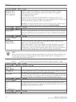
Only the fundamental harmonic is evaluated, higher harmonics are suppressed. This is
the standard measurement procedure of the protection functions.
True RMS
The “True” RMS value is determined, i.e. higher harmonics are evaluated. This procedure
is applied, for example, if an overload protection element must be realized on the basis of
a current measurement, as the higher harmonics contribute to thermal heating.
Parameter
MEAS. QUANTITY
=
Current
Parameter
CURRENT
Ia
Ib
Ic
In
In sensitive
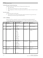
It is determined which current-measuring channel must be evaluated by the function.
Depending on the device version, either IN (normal-sensitive ground current input) or INS
(sensitive ground current input) is offered.
Parameter
MEAS. QUANTITY
=
Voltage
Parameter
VOLTAGE
Functions
2.15 Flexible Protection Functions
172
SIPROTEC 4, 7SD80, Manual
E50417-G1100-C474-A2, Edition 02.2018
Содержание SIPROTEC 4 7SD80
Страница 8: ...8 SIPROTEC 4 7SD80 Manual E50417 G1100 C474 A2 Edition 02 2018 ...
Страница 10: ...10 SIPROTEC 4 7SD80 Manual E50417 G1100 C474 A2 Edition 02 2018 ...
Страница 18: ...18 SIPROTEC 4 7SD80 Manual E50417 G1100 C474 A2 Edition 02 2018 ...
Страница 248: ...248 SIPROTEC 4 7SD80 Manual E50417 G1100 C474 A2 Edition 02 2018 ...
Страница 298: ...298 SIPROTEC 4 7SD80 Manual E50417 G1100 C474 A2 Edition 02 2018 ...
Страница 312: ...312 SIPROTEC 4 7SD80 Manual E50417 G1100 C474 A2 Edition 02 2018 ...
Страница 322: ...322 SIPROTEC 4 7SD80 Manual E50417 G1100 C474 A2 Edition 02 2018 ...
Страница 400: ...400 SIPROTEC 4 7SD80 Manual E50417 G1100 C474 A2 Edition 02 2018 ...
Страница 402: ...402 SIPROTEC 4 7SD80 Manual E50417 G1100 C474 A2 Edition 02 2018 ...

