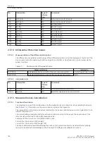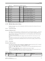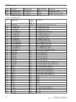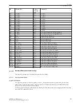
General Trip
All trip signals for the protection functions are connected by OR and generate the indication
Relay TRIP
.
This indication can be routed to LED or output relays.
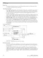
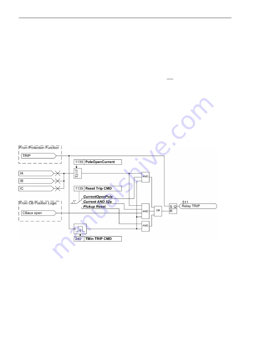
Terminating the Trip Signal
A trip command once transmitted is stored (see
). At the same time, the minimum trip command
duration
TMin TRIP CMD
is started. It ensures that the command is transmitted to the circuit breaker for a
sufficient amount of time, even if the tripping protection function drops out very quickly. The trip commands
can only be reset after all tripping protection functions have dropped out and after the minimum trip
command time has elapsed.
A further condition for terminating the trip command is that the circuit breaker is recognized to be open. The
function control of the device checks this condition by means of the circuit-breaker position feedback (Section
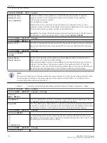
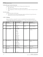
“Detection of the Circuit-Breaker Position”) and the flow of current. In address 1130 the residual current
PoleOpenCurrent
is set which is certainly undershot when the circuit-breaker pole is open. Address 1135
Reset Trip CMD
determines under which conditions a trip command is reset. If
CurrentOpenPole
is set,
the trip command is reset as soon as the current disappears. It is important that the value falls below the
setting in address 1130
PoleOpenCurrent
(see above). If
Current AND 52a
is set, the circuit-breaker
auxiliary contact must also send a message that the circuit breaker is open. This setting requires the position
of the auxiliary contact to be routed via a binary input. If this additional condition is not required for resetting
the trip command (e.g. if test sockets are used for protection testing), it can be switched off with the setting
Pickup Reset
.
[lo-ls-absteuer-ausloese-20101112, 1, en_US]
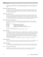
Figure 2-78
Storage and termination of the trip command
Reclosure Interlocking
After the circuit breaker has been tripped by a protection function, the reclosing must often be blocked until
the cause for tripping of the protection function has been found. 7SD80 enables this via the integrated reclo-
sure interlocking.
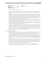
The interlocking state (“LOCKOUT”) will be realized by an RS flipflop which is protected against auxiliary
voltage failure (see
). The RS flipflop is set via binary input
>Lockout SET
(no. 385). With the
output indication
LOCKOUT
(no. 530), if interconnected correspondingly, reclosing of the circuit breaker (e.g.
for automatic reclosing, manual close signal, closing via control) can be blocked. The interlocking should only
be reset manually via binary input
>Lockout RESET
(no. 386) when the cause of the fault has been deter-
mined.
Functions
2.16 Function Logic
178
SIPROTEC 4, 7SD80, Manual
E50417-G1100-C474-A2, Edition 02.2018
Содержание SIPROTEC 4 7SD80
Страница 8: ...8 SIPROTEC 4 7SD80 Manual E50417 G1100 C474 A2 Edition 02 2018 ...
Страница 10: ...10 SIPROTEC 4 7SD80 Manual E50417 G1100 C474 A2 Edition 02 2018 ...
Страница 18: ...18 SIPROTEC 4 7SD80 Manual E50417 G1100 C474 A2 Edition 02 2018 ...
Страница 248: ...248 SIPROTEC 4 7SD80 Manual E50417 G1100 C474 A2 Edition 02 2018 ...
Страница 298: ...298 SIPROTEC 4 7SD80 Manual E50417 G1100 C474 A2 Edition 02 2018 ...
Страница 312: ...312 SIPROTEC 4 7SD80 Manual E50417 G1100 C474 A2 Edition 02 2018 ...
Страница 322: ...322 SIPROTEC 4 7SD80 Manual E50417 G1100 C474 A2 Edition 02 2018 ...
Страница 400: ...400 SIPROTEC 4 7SD80 Manual E50417 G1100 C474 A2 Edition 02 2018 ...
Страница 402: ...402 SIPROTEC 4 7SD80 Manual E50417 G1100 C474 A2 Edition 02 2018 ...


