


3. Select SIEMENS telegram 390, 391 or 392 as telegram type. A maximum of eight output
cams can be configured for each telegram. The number of DI/DO is limited to eight, i.e.
only two output cams can be configured for telegram 392 if you are already using six
measuring inputs. Therefore consider whether you also want to use measuring inputs
during the telegram selection.
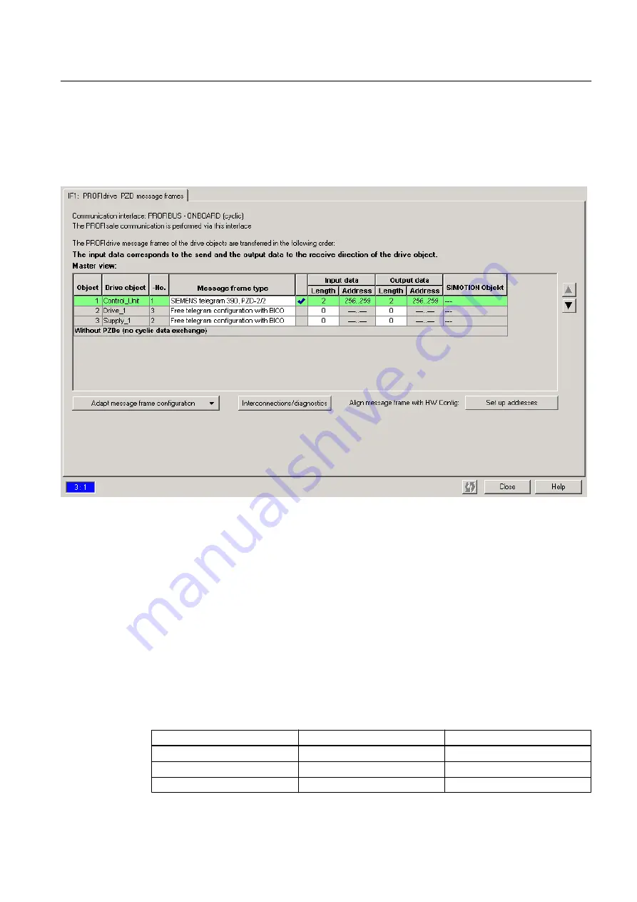
Figure 3-24 Determining the hardware address of the components
4. Before you determine the hardware address, an alignment between HW Config and
SIMOTION SCOUT, with respect to the address, must be performed. If this has not been
performed or you have changed the addresses, click on Set up addresses. If there are
question marks in the fields instead of I/O addresses, you must also perform an alignment.
5. Now calculate the hardware address by adding the base output address (first value of the
output data) of the Control Unit to the offset (for example 298 + 3 = 301). The offset always
has the value 3. Enter this calculated address under Measuring input > Configuration >
Input (e.g. PI 301.1)."]
6. The onboard measuring inputs in the expert list of the Control Unit must be set in parameters
680[0] to 680[5] (e.g. 680[0] -> [1] DI/DO 9 (X122.8/X121.8))." You will find the bit number
in the following table. The inputs are set in parameters 680.0 to 680.7 of the Control Unit,
e.g. bit 1 in parameter 680[0].
Table 3-7
Bit numbers for D410 and D4x5
Output D4x5
Output D410
Bit number
X122.7 (DI/DO 8)
X121.7 (DI/DO 8)
Bit 0
X122.8 (DI/DO 9)
X121.8 (DI/DO 9)
Bit 1
X122.10 (DI/DO 10)
X121.10 (DI/DO 10)
Bit 2
Output Cam TO - Part I
3.3 Configuring the Output Cam technology object
Output Cams and Measuring Inputs
Function Manual, 04/2014
49


