


Field/Button
Meaning/Note
Last programmed ON
duration
(See Section Time-
based cam)
Enter the ON duration for time-based cams here. The output cam switches off once the
parameterized time has expired.
Max. ON length
(See Section Time-
based cam with
maximum ON length)
Enter the maximum ON length for time-based cams with maximum ON length here.
4.3.6
Configuring cam tracks on SIMOTION D4xx onboard
Output cams and cam tracks can be configured for standard outputs, or as high-speed,
hardware-based output cams / cam tracks.
A cam track can be configured on SIMOTION D4xx onboard as follows:
1. In the project navigator, switch to the Control Unit via SINAMICS_Integrated > Control_Unit.
2. Double-click Inputs/outputs below the control unit. The window appears on the workspace.
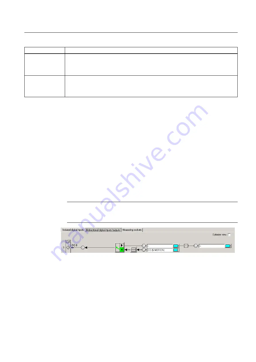
3. Switch to the Bidirectional digital inputs/outputs tab.
4. Click the button to switch between the input and output for the digital inputs/outputs (DO8
to DO15). In each case, switch the DI/DO to the output you wish to use as the output of
output cam. The designation at the terminal strip of DI or DO switches to DO. Outputs of
the output cam can only be used if they have been defined as an output. DO 8 is configured
as an output in the diagram. For the output, select the DO (SIMOTION) setting.
Note
Mixed use of the SIMOTION D4xx DI/O as high-speed outputs (of output cams) and inputs
of measuring inputs is possible.
Figure 4-24 SIMOTION D4xx digital inputs/outputs
5. Click Close.
6. Insert a new output cam or a new cam track or use an existing one.
7. Parameterize the TO Output Cam / Cam Track
8. Double-click Configuration below the output cam or the cam track in the project navigator.
The Configuration window appears in the working area.
Cam Track TO - Part II
4.3 Configuring the TO Cam Track
Output Cams and Measuring Inputs
Function Manual, 04/2014
109


