


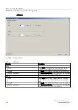


8. Activate the option Standard (global measuring input). Assignment of an output to a
measuring input is supported as of V4.2 by symbolic assignment (see Chapter Symbolic
Assignment (as of V4.2) in the SIMOTION Runtime Basic Functions manual) or by entering
the hardware address. In order to assign a physical output, the HW address and bit number
must be entered in the Output field.
9. Click OK to close the window and select Project > Save.
This is how you determine the logical hardware address for the onboard inputs of D4xx, D410-2, D4x5-2
(X122/X132), CX32, CX32-2, CU310, CU310-2, CU320, CU320-2 (only if no symbolic assignment is
activated)
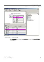
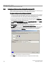
1. In the project navigator, select Communication > Telegram configuration under the
SIMOTION or SINAMICS device.
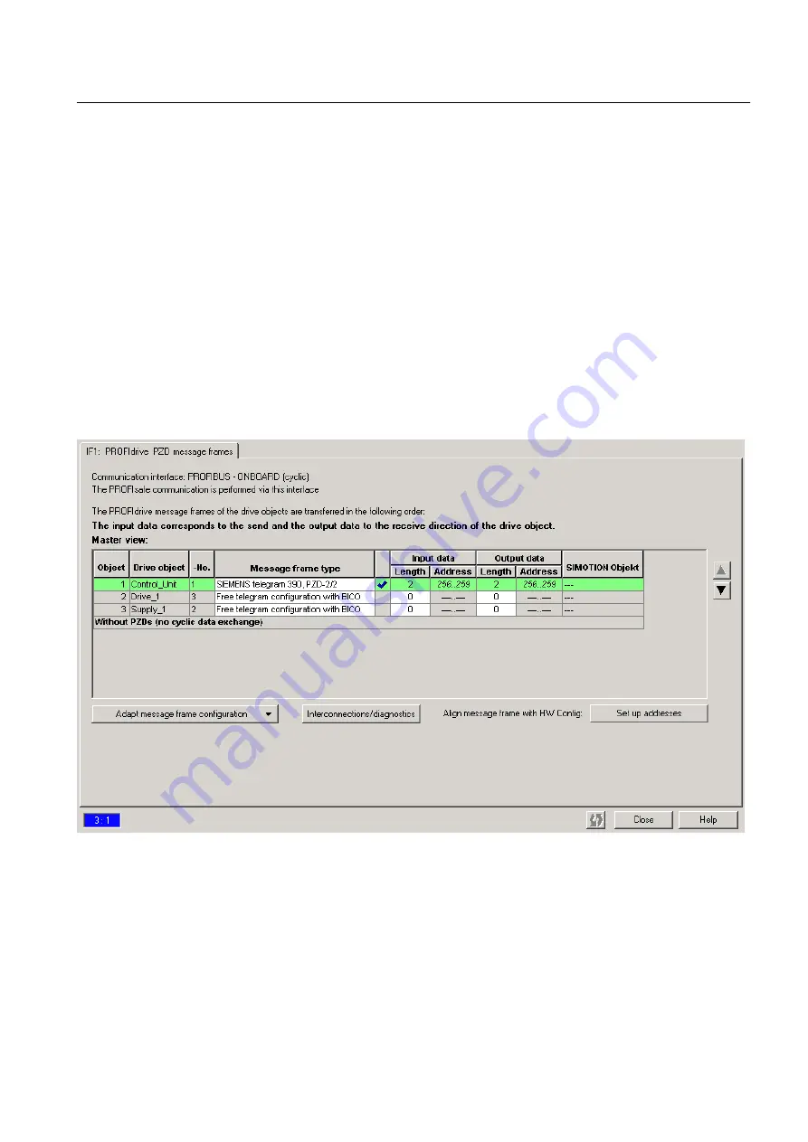
2. Double-click Telegram configuration and, in the window that opens, select the tab
PROFIdrive PZD telegrams. The components are displayed there with address range (input/
output data).
Figure 5-18 Control unit I/O addresses
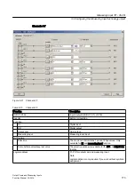
3. Select the telegram type SIEMENS telegram 391 (max. 2 measuring inputs), 392 (max. 6
measuring inputs) or 393/396 (max. 8 measuring inputs only D410-2/CU310-2/D4x5-2/
CU320-2). The message depends on the number of measuring inputs configured.
4. Before you determine the hardware address, an alignment between HW Config and
SIMOTION SCOUT, with respect to the address, must be performed. If this has not been
performed or you have changed the addresses, click on Set up addresses. If there are
question marks in the fields instead of I/O addresses, you must also perform an alignment.
Measuring Input TO - Part III
5.3 Configuring the Measuring Input technology object
Output Cams and Measuring Inputs
Function Manual, 04/2014
169


