


● Within the hysteresis, the switching state of position-based cams is not changed.
● If modified switching conditions for the output cam are detected when the output cam is
outside the hysteresis range, this current switching state is set.
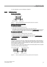
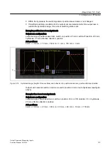
Example: position-based cam hysteresis
Output cam configuration:
output cam type: position-based cam; switch-on position, 20 mm; switch-off position, 200 mm;
hysteresis, 20 mm; effective direction: positive
Axis positions:
0 mm -> 100 mm -> 10 mm -> 50 mm -> 0 mm -> 150 mm -> 0 mm
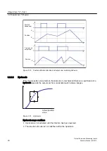
+\VWHUHVLV
$FWXDOSRVLWLRQRID[LV
;
VWDUW
6ZLWFKLQJVWDWHRISRVLWLRQEDVHGFDP
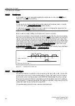
Figure 3-15 Hysteresis range (height of blue sections) and behavior of a position-based cam, positive effective direction
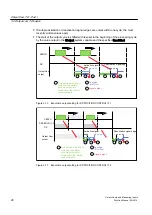
Output cam's second switch-on point is moved to position 30 mm, due to hysteresis (see figure
above).
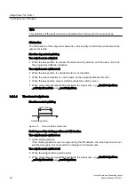
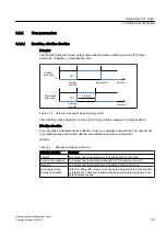
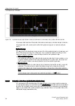
Example: time-based cam hysteresis
Output cam configuration:
output cam type: time-based cam; switch-on position, 40 mm; ON duration, 0.5 s; hysteresis,
20 mm; effective direction: positive
Axis positions:
0 mm -> 100 mm -> 20 mm -> 60 mm -> 30 mm -> 80 mm -> 10 mm -> 150 mm
Output Cam TO - Part I
3.2 Output cam TO basics
Output Cams and Measuring Inputs
Function Manual, 04/2014
31


