


4.3.12.4
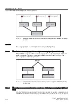
Relative edge-controlled
You can use the user program to implement a relative, edge-controlled enable input for a cam
track.
Follow the steps outlined below:
1. Configure the cam track.
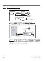
2. Configure a measuring input that detects the measured result for exchanging the cam track
(e.g. position of a workpiece edge).
The measuring input can be connected, for example, to a drive via PROFIBUS DP, a
SIMOTION CPU, or a TM15/TM17 High Feature. Unintended edges apparent during
measuring can be hidden using the measuring range.
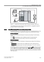
3. Depending on the measured position, the configured cam track can be activated with
_enableCamTrack in the user program and the detected position can be calculated via the
axis reference position. Cam track output then occurs relative to the measured position.
Note that output cams cannot be output immediately after the measurement has taken place,
due to data transfer times (for example bus runtimes).
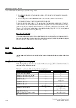
This must be taken into account as follows in your application:
● A certain time interval should be left between the measurement and output of the first output
cam.
● The edge-detecting sensor should be positioned in the machine accordingly.
Cam Track TO - Part II
4.3 Configuring the TO Cam Track
Output Cams and Measuring Inputs
122
Function Manual, 04/2014


