


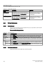


Hardware (measuring inputs)
Local measuring inputs
Global measuring inputs
SIMODRIVE 611U
X
-
ADI4, IM174
X
-
PROFIdrive units
X
-
IM174/ADI4
X
-
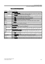
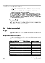
Quantity structures for hardware measuring inputs
Table 5-2
Measuring inputs - Overview of quantity structures and functionality
Maximum available
quantity structure
Maximum number of
measuring input inputs
Can be configured as a
local measuring input
Can be configured as a
global measuring input
CU310, D410, CX32
3
X
X
D4x5, CU320
6
X
X
D4x5-2
16
Max. 8
Max. 16
CU320-2, CU310-2,
D410-2, CX32-2
8
X
X
CX32-2
4
X
X
C230-2
2
2 (M1, M2)
-
C240
6
2 (M1, M2
4 (B1-B4)
C240 PN
4
-
4 (B1-B4)
TM15
24
-
X
TM17 High Feature
16
-
X
5.2.3
Interconnections
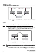
The Measuring Input TO can be linked to all technology objects, such as Axis TO (positioning
axis, following axis, path axis) and External Encoder TO.
A TO, such as an Axis TO, can be interconnected simultaneously with several Measuring Input
TOs. The assignment can be configured.
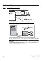
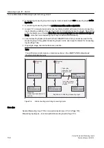
With local measuring inputs, the measuring input TO is assigned symbolically or if <V4.2 as
part of its configuration. The configuration specifies the number of the measuring input to be
used and the number of the encoder on the assigned axis.
(See also Local measuring (Page 163))
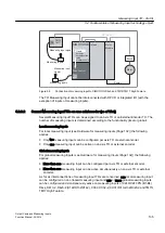
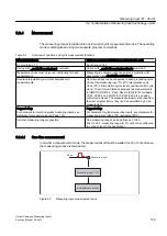
With global measuring inputs, the HW address is used for assignment to the measuring input.
(See also Global measuring (Page 164))
With V4.2 and higher, global measuring inputs can also be configured with symbolic
assignments. Address handling is thereby no longer required.
Measuring Input TO - Part III
5.2 Fundamentals of Measuring Input technology object
Output Cams and Measuring Inputs
Function Manual, 04/2014
133


