


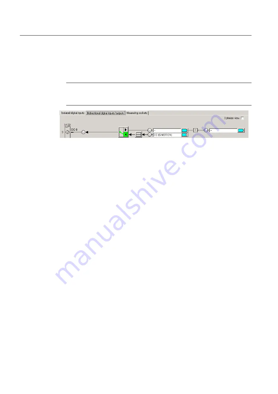
4. Click the button to switch between the input and output for the digital inputs/outputs (DO8
to DO15). In each case, switch the DI/DO to the output you wish to use as the output of
output cam. The designation at the terminal strip of DI or DO switches to DO. Outputs of
the output cam can only be used if they have been defined as an output. DO 8 is configured
as an output in the diagram. For the output, select the DO (SIMOTION) setting.
Note
Mixed use of the SIMOTION D4xx DI/O as high-speed outputs (of output cams) and inputs
of measuring inputs is possible.
Figure 3-23 SIMOTION D4xx digital inputs/outputs
5. Click Close.
6. Insert a new output cam or a new cam track or use an existing one.
7. Parameterize the TO Output Cam / Cam Track
8. Double-click Configuration below the output cam or the cam track in the project navigator.
The Configuration window appears in the working area.
9. For high-speed, hardware-supported output cams, you can achieve an output accuracy
exceeding the servo cycle clock based on the hardware used. Should you wish to configure
a high-speed output cam, select the Activate output check box and select the High-speed
digital output (DO) radio button.
10.Assignment of an output to an output cam/cam track is supported as of V4.2 either by
symbolic assignment (see Chapter Symbolic Assignment (as of V4.2) in the SIMOTION
Runtime Basic Functions manual) or by entering the hardware address.
11.Click OK to close the window and select Project > Save.
To determine the logical hardware address for outputs on SIMOTION D4xx onboard (only if
symbolic assignment is not activated)
1. In the project navigator, below the SIMOTION D device, select SINAMICS_Integrated >
Communication > Telegram configuration.
2. Double-click Configuration and, in the window which appears, select the tab IF1:
PROFIdrive PZD telegram. The components are displayed there with address range (input/
output data).
Output Cam TO - Part I
3.3 Configuring the Output Cam technology object
Output Cams and Measuring Inputs
48
Function Manual, 04/2014


