System overview
2.1 What is the S7-1500R/H redundant system?
S7-1500R/H redundant system
System Manual, 10/2018, A5E41814787-AA
25
2.1.3
Plant components and automation levels
Plant components and automation levels
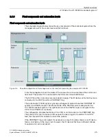
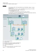
The schematic diagram below shows the key components of the redundant system from the
management level to the control level and the field level.
Figure 2-6
Possible configuration at the management, control and field level using the example of S7-1500R
From the management level, the master PC accesses the various devices at the control and
field level. The master PC is connected to the CPUs over Industrial Ethernet.
The R-CPUs at the control level are redundant in design. The IO devices at the field level are
connected to the R-CPUs within a PROFINET ring.
The redundant S7-1500R system cyclically exchanges IO data with another PROFINET IO
system via a PN/PN coupler. The left-hand side of the PN/PN coupler is assigned to the
S7-1500R redundant system. The right-hand side of the PN/PN coupler is assigned to the
CPU 1516-3 PN/DP (IO controller).
The configuration tolerates the failure of one CPU or an interruption in the PROFINET ring.
The primary CPU and the backup CPU execute the user program in parallel. If one CPU
fails, the second CPU maintains control of the process.
If the PROFINET ring is interrupted, for example as a result of a cable break or an IO device
failure, redundancy in the ring is lost. However, the IO devices that have not failed continue
to operate and can be accessed.
Содержание Simatic S7-1500H
Страница 1: ......


