background image


Commissioning 


9.4 Operating and system states 

S7-1500R/H redundant system 
System Manual, 10/2018, A5E41814787-AA 

199


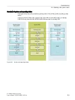
Overview of system and operating states 

The figure below shows the possible operating states of the CPUs and the resulting system 

states. 
In general, the two CPUs have equal priority; each CPU can be either primary or backup. 

The CPU that you switch from STOP to RUN first becomes the primary CPU. 


Figure 9-6 

System and operating states 

Содержание Simatic S7-1500H

Страница 1: ......

Страница 2: ..._________________ ___________________ ___________________ ___________________ SIMATIC S7 1500 S7 1500R H redundant system System Manual 10 2018 A5E41814787 AA Preface Documentation guide 1 System overview 2 Application planning 3 Installation 4 Wiring 5 Configuration 6 Basics of program execution 7 Protection 8 Commissioning 9 Display 10 Maintenance 11 Test functions 12 Technical specifications 13...

Страница 3: ...ly by personnel qualified for the specific task in accordance with the relevant documentation in particular its warning notices and safety instructions Qualified personnel are those who based on their training and experience are capable of identifying risks and avoiding potential hazards when working with these products systems Proper use of Siemens products Note the following WARNING Siemens prod...

Страница 4: ...ocumentation This documentation applies to all products of the SIMATIC S7 1500R H redundant system Conventions STEP 7 In this documentation STEP 7 is used as a synonym for all versions of the configuration and programming software STEP 7 TIA Portal Please also see the notes indicated as follows Note A note contains important information on the product described in the documentation on the handling...

Страница 5: ...development to make them more secure Siemens strongly recommends that product updates are applied as soon as they are available and that the latest product versions are used Use of product versions that are no longer supported and failure to apply the latest updates may increase customers exposure to cyber threats To stay informed about product updates subscribe to the Siemens Industrial Security ...

Страница 6: ... The Industry Mall is the catalog and order system of Siemens AG for automation and drive solutions on the basis of Totally Integrated Automation TIA and Totally Integrated Power TIP You can find catalogs for all automation and drive products on the Internet https mall industry siemens com ...

Страница 7: ...vice IP addresses 43 2 4 2 Integrated interfaces for communication 45 2 4 3 HMI devices 46 2 5 Power supply 46 2 6 Software 47 2 6 1 TIA Portal 47 2 6 2 SINETPLAN 48 2 6 3 PRONETA 48 3 Application planning 49 3 1 Requirements 49 3 2 Restrictions compared to the S7 1500 automation system 51 3 3 Configuration versions 54 3 3 1 S7 1500R H configuration with IO devices in the PROFINET ring 55 3 3 2 S7...

Страница 8: ... 90 3 8 Using HMI devices 92 4 Installation 96 4 1 Basics 96 4 2 Installing the mounting rail 98 4 3 Installing a load current supply 102 4 4 Installing a system power supply 104 4 5 Installing R H CPUs 106 5 Wiring 108 5 1 Rules and regulations for operation 108 5 2 Operation on grounded infeed 110 5 3 Electrical configuration 113 5 4 Wiring rules 114 5 5 Connecting the supply voltage 115 5 6 Con...

Страница 9: ...f the protection functions 168 8 2 Configuring access protection for the CPU 168 8 3 Using the display to set additional password protection 172 8 4 Using the user program to set additional access protection 172 8 5 Know how protection 173 8 6 Protection by locking the CPU 177 9 Commissioning 178 9 1 Overview 178 9 2 Check before powering on for the first time 179 9 3 Commissioning procedure 180 9...

Страница 10: ...ction with S7 1500H 263 11 1 3 3 Replacing defective synchronization module with S7 1500H 263 11 1 3 4 Replacing both defective redundancy connections with S7 1500H 264 11 1 4 Replacing defective PROFINET cables 265 11 1 5 Replacing a defective SIMATIC memory card 266 11 1 6 Replacing a defective system power supply PS or load power supply PM 267 11 1 7 Replacing defective IO devices switches 268 ...

Страница 11: ... Manual 10 2018 A5E41814787 AA A Dimension drawings 302 B Accessories spare parts 305 C Safety symbols 307 C 1 Safety related symbols for devices without Ex protection 307 C 2 Safety related symbols for devices with Ex protection 308 Glossary 310 Index 323 ...

Страница 12: ...nd programming Device information Product manuals contain a compact description of the module specific information such as properties wiring diagrams characteristics and technical specifications General information The function manuals contain detailed descriptions on general topics regarding the redundant S7 1500R H system e g diagnostics communication You can download the documentation free of c...

Страница 13: ...on area In addition your data is already filled out in support requests and you can get an overview of your current requests at any time You must register once to use the full functionality of mySupport You can find mySupport on the Internet https support industry siemens com My ww en mySupport Documentation In the Documentation area in mySupport you can combine entire manuals or only parts of the...

Страница 14: ...LAN SINETPLAN the Siemens Network Planner supports you in planning automation systems and networks based on PROFINET The tool facilitates professional and predictive dimensioning of your PROFINET installation as early as in the planning stage In addition SINETPLAN supports you during network optimization and helps you to exploit network resources optimally and to plan reserves This helps to preven...

Страница 15: ...s control of the process Aims of using redundant automation systems Redundant automation systems are used in practice to achieve greater availability or fail safety Purpose of fault tolerant systems to reduce the probability of production downtime by operating two systems in parallel Purpose of fail safe systems to protect life the environment and capital with safe shutdown to a secure state WARNI...

Страница 16: ...imes and the consequences of component errors The higher the risks and costs of a production downtime the more worthwhile the use of a redundant system You can compensate for the generally higher investment costs by avoiding production downtimes Use In redundantly operated systems failure or malfunction of individual automation components must not impede the operation of the plant S7 1500R H redun...

Страница 17: ...tion solution controls the fan speeds in line with the measured pollutant concentration Three sensors in the tunnel measure the pollutant levels in the air The S7 1500H redundant system with two redundant CPUs is used to ensure fan availability As well as controlling the fans the S7 1500H redundant system also controls the illumination and the traffic lights Figure 2 1 Example Tunnel automation Be...

Страница 18: ...ls and that the warehouse can continue to operate Solution To store goods in and retrieve them from the bays the storage and retrieval unit moves along an X Y and Z axis If the process is interrupted data can be lost and the location of the goods is not known To guard against the loss of data the storage and retrieval unit is controlled by the S7 1500R redundant system Figure 2 2 Example High bay ...

Страница 19: ...interrupted The pig iron then cannot be used for the production of steel The automation solution must ensure that the plant continues to run if a CPU fails and that the material is not damaged Solution The S7 1500R redundant system controls the blast furnace The distributed automation components of the redundant system control the temperature volume and pressure parameters Figure 2 3 Example Blast...

Страница 20: ...ms tolerate the failure of one of the two CPUs or an interruption in the PROFINET ring The S7 1500R and S7 1500H systems differ in structure configuration limits and performance S7 1500 design and operating principle The figure below shows the typical structure of the S7 1500R redundant system S7 1500R CPU PROFINET cable redundancy connections PROFINET ring IO device Switch Figure 2 4 Structure of...

Страница 21: ...ncy connections in an S7 1500R system are the PROFINET ring with MRP The two CPUs must be directly connected to each other with a PROFINET cable All nodes can still communicate with each other in the event of an interruption in the ring PROFINET devices that do not support MRP must be separated from the ring with a switch One of the two CPUs in the redundant system takes on the role of primary CPU...

Страница 22: ...l 10 2018 A5E41814787 AA 21 S7 1500H structure and operating principle The figure below shows the typical structure of the S7 1500H redundant system S7 1500H CPU PROFINET cable PROFINET ring Redundancy connections fiber optic cables IO device Switch Figure 2 5 Structure of an S7 1500H redundant system ...

Страница 23: ...dundancy S2 As with S7 1500R the S7 1500H redundant system requires a PROFINET ring closed by the CPUs All nodes can still communicate with each other in the event of an interruption in the ring Devices that do not support MRP must be separated from the ring with a switch Unlike in S7 1500R the PROFINET ring and redundancy connections in S7 1500H are separate The two redundancy connections are fib...

Страница 24: ...T ring The H Sync forwarding function is recom mended for all nodes in the PROFINET ring Part of the bandwidth on the PROFINET cable is required for synchronization of the CPUs Less bandwidth is therefore available for PROFINET IO communication Each CPU has two optical interfaces Synchronization of the CPUs runs separately from the PROFINET ring over fiber optic ca bles The full bandwidth of the P...

Страница 25: ...U 1515 2 PN CPU 1517 3 PN DP CPU 1513F 1 PN CPU 1515F 1 PN CPU 1517F 3 PN DP CPU 1513R 1 PN CPU 1515R 2 PN CPU 1517H 3 PN Support for distributed I O Configuration control Web server CPU redundancy System redundancy S2 Isochronous mode Shared Device IRT MRP MRPD OPC UA Motion Control PID control 1 Security Integrated Protection function Copy protection Safety mode 2 Integrated system diagnostics 1...

Страница 26: ...rol level are redundant in design The IO devices at the field level are connected to the R CPUs within a PROFINET ring The redundant S7 1500R system cyclically exchanges IO data with another PROFINET IO system via a PN PN coupler The left hand side of the PN PN coupler is assigned to the S7 1500R redundant system The right hand side of the PN PN coupler is assigned to the CPU 1516 3 PN DP IO contr...

Страница 27: ...N or using an additional switch S7 1500R supports the following number of PROFINET devices switches S7 1500R H CPUs S7 1500 CPUs V2 5 or later HMI devices and IO devices such as ET 200MP and ET 200SP In the PROFINET ring max 50 recommended max 16 In the PROFINET ring and separated with switches line max 66 Note Recommendation for S7 1500R Operate a maximum of 16 PROFINET devices including R CPUs i...

Страница 28: ...y connections in S7 1500R are the PROFINET ring with MRP The CPUs are synchronized over the PROFINET ring Load power supply optional CPU S7 1515R 2 PN PROFINET cable redundancy connections PROFINET ring IO device in the PROFINET ring Switch IO device outside the PROFINET ring separated with a switch Figure 2 7 S7 1500R configuration version ...

Страница 29: ...5 or later and HMI devices In the PROFINET ring max 50 In the PROFINET ring and separated with switches line max 258 The redundancy connections in S7 1500H are two duplex fiber optic cables that connect the CPUs directly with plug in synchronization modules Load power supply optional CPU 1517H 3 PN PROFINET cable redundancy connections PROFINET ring Redundancy connections two duplex fiber optic ca...

Страница 30: ...em S7 1500R H redundant system System Manual 10 2018 A5E41814787 AA 29 2 1 5 Overview of features The S7 1500R H redundant system meets all the requirements for a fault tolerant system The figure below sets out the main features Figure 2 9 S7 1500R H features ...

Страница 31: ...ds PROFINET cable redundancy connections PROFINET ring IO devices Load power supply optional System power supply optional The S7 1500R redundant system should be installed either on one shared mounting rail or on two separate mounting rails Connecting the PROFINET cable to the PROFINET interfaces X1 P2 R of the CPUs directly connects the two CPUs You set up the PROFINET ring from the first CPU to ...

Страница 32: ... redundant system comprises the following components Two H CPUs Two SIMATIC memory cards Four synchronization modules two synchronization modules in each H CPU Two redundancy connections two duplex fiber optic cables IO devices Load power supply optional System power supply optional The S7 1500H redundant system should be installed either on one shared mounting rail or on two separate mounting rai...

Страница 33: ...Configuration example Optional load or system power supply CPU with two synchronization modules connected underneath not visible in the diagram Mounting rail with integrated DIN rail profile Redundancy connections fiber optic cables PROFINET cable PROFINET ring Figure 2 11 S7 1500H configuration example ...

Страница 34: ...il The screw set is inserted in the mounting rail s T profile groove and is required for grounding the mounting rail The set of screws is included in the scope of delivery of the mounting rails in the standard lengths 160 mm to 830 mm and can be ordered as Accessories spare parts Page 305 R H CPUs The CPU runs the user program Additional features and functions of the CPU Communication via Industri...

Страница 35: ... volt age The 4 pin connection plug provides the supply voltage System power supply PS The system power supply can be connected to the backplane bus using a U connector In the S7 1500R H redundant sys tem the system power supply does not support diagnostics Various models of system power supplies are available PS 25 W 24 V DC PS 60 W 24 48 60 V DC PS 60 W 24 48 60 V DC HF Extended retentivity of t...

Страница 36: ...U 1517H 3 PN Data work memory max 1 5 MB 3 MB 8 MB Code work memory max 300 KB 500 KB 2 MB Plug in load memory SIMATIC memory card max 32 GB 32 GB 32 GB I O address area max 32 KB 32 KB 32 KB 32 KB 32 KB 32 KB PROFINET IO interfaces 1 1 1 PROFINET interfaces 1 1 Processing time for bit operations 0 04 μs 0 03 μs 0 002 μs Display screen size 3 45 cm 6 1 cm 6 1 cm Suitable PROFINET devices switches ...

Страница 37: ...he MRP media redundancy protocol S7 1500R uses the PROFINET ring to synchronize the two CPUs S7 1500H uses the redundancy connections over fiber optic cables to synchronize the two CPUs The PROFINET ring over PROFINET interfaces X1 of the H CPUs is also mandatory for S7 1500H To set up a ring topology with media redundancy you need to bring together the free ends of a linear network topology in on...

Страница 38: ...he RUN Redundant system state Both CPUs are IO controllers PROFINET communication runs on both system redundancy ARs simultaneously in each case between one of the CPUs IO controller and the IO device If the primary CPU then fails the backup CPU becomes the primary CPU and also switches the backup AR to primary AR The data of this AR then becomes active at the outputs Behavior in the RUN Solo syst...

Страница 39: ... access and modifications to algorithms with password protection CPU lock Protection against unauthorized access by locking the front cover with a seal or a lock Access protection example You can choose from four different access levels in the TIA Portal to restrict user access to functions and memory areas Figure 2 12 Access protection If you only want to allow users access over HMI for example s...

Страница 40: ...nt of a comprehensive industrial security concept Please note the additional information on Industrial Security http www siemens com industrialsecurity 2 3 4 Diagnostics All levels of automation in the S7 1500R H redundant system have integrated diagnostics All SIMATIC products have integrated diagnostic functions that you can use to analyze localize and log faults and errors efficiently System di...

Страница 41: ... in the configuration and programming software TIA Portal on the HMI devices and on the CPU displays Figure 2 13 Overview of system diagnostics in a plant Advantages and customer benefits Integrated system diagnostics offers the following advantages Diagnostics is always consistent with the actual state of the plant In S7 1500R H redundant mode the diagnostic information is synchronized between th...

Страница 42: ...ates troubleshooting and optimization for the user program Trace records device tags and evaluates the recordings This allows you to analyze defective signal responses Tags are for example drive parameters or the system and user tags of a CPU Because the CPU records tags directly the trace and logic analyzer function is suitable for monitoring highly dynamic processes Note Trace restrictions The S...

Страница 43: ...isplays the selected signals of a recording Bits are shown in the lower diagram as a bit track The signal table lists the signals of the selected measurement and provides setting options for specific properties Trace recordings for S7 1500R H in the project tree Trend diagram Signal table Figure 2 14 Trace measurement for S7 1500R H Advantages and customer benefits The trace function offers the fo...

Страница 44: ...e on the right hand side of each CPU System IP addresses In addition to the device IP addresses of the CPUs the redundant system S7 1500R H supports system IP addresses System IP address for the X1 PROFINET interfaces of the two CPUs system IP address X1 System IP address for the X2 PROFINET interfaces of the two CPUs system IP address X2 You use the system IP addresses for communication with othe...

Страница 45: ...s Configuration example The figure below shows a configuration in which the S7 1500R H redundant system communicates with other devices over the system IP address X2 The other devices are connected to the S7 1500 redundant system over the X2 PROFINET interfaces Figure 2 15 Example Communication of the S7 1500R H redundant system over the system IP address X2 Reference You can find more information...

Страница 46: ...network topology detection PG communication for commissioning testing and diagnostics HMI communication for operator control and monitor ing 2 2 Open User Communication 3 3 Data exchange via HTTP S for example for diagnos tics Time synchronization 1 Not with CPU 1513R 1 PN 2 Communication mainly over system IP address If the CPU with the device IP address fails communication with the HMI device al...

Страница 47: ...ww en view 59192925 You can find an overview of all available HMI devices in the Industry Mall https mall industry siemens com mall en WW Catalog Products 9109999 tree CatalogTre e 2 5 Power supply The CPUs of the redundant system have an integrated system power supply It provides the necessary power to the backplane bus You can add one load power supply or one system power supply each to the inte...

Страница 48: ...ntrollers are integrated into the Totally Integrated Automation Portal Engineering with TIA Portal offers Configuration and programming Shared data management A uniform operating concept for control visualization and drives The TIA Portal simplifies integrated engineering in all configuration phases of a plant Figure 2 16 TIA Portal overview ...

Страница 49: ...tion plant and helps improve operational safety The advantages at a glance Network optimization thanks to port specific calculation of the network load Increased production availability thanks to online scan and verification of existing systems Transparency before commissioning with the import and simulation of existing STEP 7 projects Efficiency through securing existing investments in the long t...

Страница 50: ... the S7 1500R H redundant system Hardware requirements Table 3 1 Hardware requirements Property Requirement S7 1500R H CPUs Two identical R or H CPUs in the redundant system Identical article numbers function versions and firmware versions for the two CPUs PROFINET ring A PROFINET ring is required for all configuration versions Page 54 of the S7 1500R H redundant system ...

Страница 51: ...e for each of the two R H CPUs For all other devices in the PROFINET ring set Client as the media redundancy role PROFINET devices that do not support system redundancy S2 can be located in the PROFINET ring or be separated with a switch Switches without system redundancy S2 Set the media redundancy role to Client over the Web interface Configure the ring ports in line with the wiring HMI devices ...

Страница 52: ...1500 automation system Introduction Please note the following restrictions with the S7 1500R H redundant system compared to the S7 1500 automation system Hardware restrictions Table 3 3 Hardware restrictions Property Restriction Fail safe modules Fail safe modules are not supported in the S7 1500R H re dundant system Power segment overview with system power supply Not supported Series machine proj...

Страница 53: ...ly programmed connections are supported Motion Control Motion Control functions are not supported in the CPUs MRPD Not supported Multiuser Engineering Not supported Online functions Download not possible in the RUN Redundant system state SIMATIC Automation Tool SAT tool not supported OPC UA OPC UA server and client not supported PID controller Compact PID controllers not supported PID_Compact PID_...

Страница 54: ...ger access the IO devices in the PROFINET ring The IO devices will return to the sub stitute values The redundant system will not execute a primary backup switchover The redundant system will remain in the RUN Redundant system state Isochronous mode Isochronous mode is not supported Test function Testing with break points Not supported In STEP 7 the message The device does not support breakpoints ...

Страница 55: ...0R H redundant system A PROFINET ring is essential in all configuration versions For the configuration versions of the S7 1500R H system there is redundancy for the following components R H CPUs Interfaces of synchronization Network in the PROFINET ring This section describes the admissible configuration versions and their advantages benefits The following convention applies Figure 3 1 Green traff...

Страница 56: ...es benefits The IO devices are connected in the PROFINET ring with system redundancy The redundant system continues to operate following a cable interruption anywhere in the PROFINET ring One of the two communication connections of the IO devices remains A SYNCUP is prevented S7 1500R configuration CPU 1 CPU 2 PROFINET cable redundancy connections PROFINET ring IO device ET 200MP with system redun...

Страница 57: ... 10 2018 A5E41814787 AA S7 1500H configuration CPU 1 CPU 2 Two fiber optic cables redundancy connections IO device ET 200SP with system redundancy S2 IO device ET 200MP with system redundancy S2 PROFINET cable PROFINET ring Figure 3 3 S7 1500H configuration with IO devices in the PROFINET ring ...

Страница 58: ...dditional line topology to the PROFINET ring Unlike the PROFINET ring the line topology is not redundant PROFINET IO devices assigned to the S7 1500R H system must always support system redundancy S2 These PROFINET IO devices can be located in the PROFINET ring or they can be separated with a switch S7 1500R configuration CPU 1 CPU 2 PROFINET cable redundancy connections PROFINET ring IO device ET...

Страница 59: ...8 A5E41814787 AA S7 1500H configuration CPU 1 CPU 2 Two fiber optic cables redundancy connections IO device ET 200SP with system redundancy S2 IO device ET 200MP with system redundancy S2 Switch PROFINET cable PROFINET ring HMI device Figure 3 5 S7 1500H configuration with switches and line topology ...

Страница 60: ... 4 1 Introduction Introduction This section describes possible redundancy scenarios on the basis of various different configuration versions The redundancy scenarios do not result in process restrictions In the examples shown the failures are tolerated by the redundant system The following convention applies Figure 3 6 Yellow traffic light ...

Страница 61: ...rimary CPU of the redundant system fails in the RUN Redundant system state 2 The redundant system switches to the backup CPU The backup CPU becomes the new primary CPU The redundant system switches to the RUN Solo system state You can find additional information on the RUN Solo system state in the section Operating and system states Page 197 3 The new primary CPU exchanges process data with the IO...

Страница 62: ...state Primary CPU previously backup CPU RUN operating state MAINT LED yellow light The R H system is not in the RUN Redundant system state no partner CPU found in the redundant system Backup CPU previously primary CPU failed Note To get detailed diagnostics information evaluate the diagnostics buffer Solution Replace the defective CPU You can find additional information on the procedure in the sec...

Страница 63: ...e Sequence of events 1 The backup CPU of the redundant system fails in the RUN Redundant system state 2 The redundant system switches to the RUN Solo system state You can find additional information on the RUN Solo system state in the section Operating and system states Page 197 3 The primary CPU continues to exchange process data with the IO devices 4 The redundancy of the system is restricted Th...

Страница 64: ...m RUN Solo system state Primary CPU RUN operating state MAINT LED yellow light The R H system is not in the RUN Redundant system state No partner CPU has been found in the redundant system Backup CPU failed Note To get detailed diagnostics information evaluate the diagnostics buffer Solution Replace the defective CPU You can find additional information on the procedure in the section Replacing def...

Страница 65: ...INET ring Introduction The following redundancy scenario describes the effects of a defective PROFINET cable in the PROFINET ring Redundancy scenario Primary CPU Backup CPU PROFINET cable redundancy connections PROFINET ring interrupted IO device ET 200MP IO device ET 200SP Figure 3 9 Failure of a PROFINET cable in the PROFINET ring using S7 1500R as an example ...

Страница 66: ...the primary CPU fails in addition to a PROFINET cable the backup CPU switches to the STOP operating state If the PROFINET cable is also interrupted at another point IO devices in the PROFINET ring may fail depending on the location of the interruption You can find additional information in the section Failure scenarios Page 72 Diagnostics System state operating states and error displays after the ...

Страница 67: ...ilure of a redundancy connection in S7 1500H Introduction The following redundancy scenario describes the effects of a defective redundancy connection in S7 1500H Redundancy scenario Primary CPU Backup CPU One fiber optic cable redundancy connection interrupted IO device ET 200SP IO device ET 200MP PROFINET cable PROFINET ring Figure 3 10 Failure of a redundancy connection ...

Страница 68: ...g state You can find additional information in the section Failure scenarios Page 72 Diagnostics System state operating states and error displays after the failure of a redundancy connection Redundant system RUN Redundant system state Primary CPU RUN Redundant operating state MAINT LED yellow light There is only one redundancy connection remaining in the H system Backup CPU RUN Redundant operating...

Страница 69: ...io describes the effects of a defect in each of the two redundancy connections in S7 1500H In this redundancy scenario the time between the redundancy connection failures is 1500 ms Redundancy scenario Primary CPU S7 1500H Backup CPU S7 1500H Two fiber optic cables redundancy connections interrupted IO device ET 200MP IO device ET 200SP PROFINET cable PROFINET ring Figure 3 11 Failure of both redu...

Страница 70: ...n the failure of the S7 1500R H redundant system You can find additional information in the section Failure scenarios Page 72 Diagnostics System state operating states and error displays after the failure of both redundancy connections Redundant system RUN Solo system state Primary CPU RUN operating state MAINT LED yellow light The H system is not in the RUN Redundant system state No partner CPU h...

Страница 71: ...fects of a defect in each of the two redundancy connections and in the PROFINET cable in the PROFINET ring In this redundancy scenario the time between the redundancy connection failures is 1500 ms Redundancy scenario Primary CPU Backup CPU Two fiber optic cables redundancy connections interrupted IO device ET 200SP IO device ET 200MP PROFINET cable PROFINET ring interrupted Figure 3 12 Failure of...

Страница 72: ...n the process Diagnostics System state operating states and error displays after the failure of the redundancy connections and PROFINET cable Redundant system RUN Solo system state Primary CPU RUN operating state MAINT LED yellow light The H system is not in the RUN Redundant system state No partner CPU has been found in the H system The PROFINET ring is open Backup CPU STOP operating state MAINT ...

Страница 73: ...Failure scenarios Introduction This section describes possible failure scenarios with the various configuration versions The failure scenarios lead to process restrictions In the examples shown the redundant system cannot tolerate the failures any longer The following convention applies Figure 3 13 Red traffic light ...

Страница 74: ...ET 200MP IO device ET 200SP failed Figure 3 14 Failure of an IO device in the PROFINET ring using S7 1500R as an example Sequence of events 1 An IO device in the PROFINET ring fails 2 The PROFINET ring is interrupted 3 The redundant system selects an alternative connection over the backup CPU This allows the redundant system to access all remaining IO devices in the PROFINET ring again 4 The failu...

Страница 75: ...erating state MAINT LED yellow light The PROFINET ring is open ERROR LED flashes red An IO device has failed Backup CPU RUN Redundant operating state MAINT LED yellow light The PROFINET ring is open ERROR LED flashes red An IO device has failed Note To get detailed diagnostics information evaluate the diagnostics buffer Solution Replace the defective IO device You can find additional information o...

Страница 76: ...troduction The following failure scenario describes the effects of a defective switch with line topology in the PROFINET ring Failure scenario Primary CPU Backup CPU PROFINET cable redundancy connections PROFINET ring IO device ET 200MP IO device ET 200SP Switch failed IO device ET 200SP HMI device Figure 3 15 Failure of a switch in the PROFINET ring using S7 1500R as an example ...

Страница 77: ...s and outputs have an important function in the system their failure can have a critical impact on the process Diagnostics System state operating states and error displays after the failure of a switch Redundant system RUN Redundant system state Primary CPU RUN Redundant operating state MAINT LED yellow light The PROFINET ring is open ERROR LED flashes red One or more IO devices have failed Backup...

Страница 78: ...g in S7 1500R 1500 ms apart Introduction The following failure scenario describes the effects of two cable interruptions in the PROFINET ring In this failure scenario the time between the two cable interruptions is 1500 ms Failure scenario Primary CPU Backup CPU PROFINET ring interrupted at two points IO device ET 200MP IO device ET 200SP Figure 3 16 Two cable interruptions in the PROFINET ring 15...

Страница 79: ...puts have an important function in the system their failure can have a critical impact on the process Diagnostics System state operating states and error displays after the cable interruptions Redundant system RUN Solo system state Primary CPU RUN operating state MAINT LED yellow light The R system is not in the RUN Redundant system state No partner CPU has been found in the R system The PROFINET ...

Страница 80: ... ms Introduction The following failure scenario describes the effects of two cable interruptions in the PROFINET ring In this failure scenario the time between the two cable interruptions is 1500 ms Failure scenario Primary CPU Backup CPU PROFINET ring interrupted at two points IO device ET 200MP IO device ET 200SP Figure 3 17 Two cable interruptions in the PROFINET ring within 1500 ms ...

Страница 81: ...as a cable interruption in the PROFINET ring at two points within 1500 ms Lay the PROFINET cables so that they are securely protected from damage PROFINET cables should also always be laid separately from each other This makes simultaneous damage to the PROFINET cables within 1500 ms unlikely Diagnostics System state and operating states after cable interruptions Redundant system System state defe...

Страница 82: ...dure in the section Replacing defective redundancy connections Page 261 3 5 3 3 Failure of the primary CPU when IO devices have failed in the PROFINET ring Introduction The following failure scenario describes the effects of a defective IO device in the PROFINET ring and a defective primary CPU Failure scenario Primary CPU failed 2nd failure in runtime sequence Backup CPU switches to STOP operatin...

Страница 83: ...ccess the primary CPU because the latter has failed The PROFINET ring has been interrupted at a second point and the primary CPU may still be running That is why the backup CPU does not become the primary CPU This prevents an undefined system state 6 The redundant system has failed The process is no longer controlled by the redundant system Diagnostics System state operating states and error displ...

Страница 84: ...dure in the sections Replacing defective R H CPUs Page 260 and Replacing defective I O devices switches Page 268 Note Proceed as follows if you have ensured that the CPU is still working in the STOP operating state and can access all important IO devices 1 Replace the defective IO device 2 Switch the CPU from STOP operating state to the RUN operating state 3 Replace the defective CPU Switch the ne...

Страница 85: ...ntroduction The following failure scenario describes the effects of a defect in each of the two redundancy connections in S7 1500H In this failure scenario the time between the redundancy connection failures is 1500 ms Failure scenario Primary CPU Backup CPU Two fiber optic cables redundancy connections interrupted IO device ET 200SP IO device ET 200MP PROFINET cable PROFINET ring Figure 3 19 Fail...

Страница 86: ... two redundancy connections are always separate from each other This makes simultaneous damage to the redundancy connections 1500 ms apart unlikely Diagnostics System state and operating states after the failure of both redundancy connections Redundant system System state defective undefined Each H CPU is in the RUN Solo system state Primary CPU RUN operating state MAINT LED yellow light The H sys...

Страница 87: ...in a redundancy connection and the primary CPU in S7 1500H In this failure scenario the time between the redundancy connection failure and the Primary CPU is 1500 ms Failure scenario Primary CPU failed 2nd failure in runtime sequence Backup CPU One fiber optic cable redundancy connection interrupted 1st failure in runtime sequence IO device ET 200SP IO device ET 200MP PROFINET cable PROFINET ring ...

Страница 88: ...nterrupted and the primary CPU may still be running That is why the backup CPU does not become the primary CPU This prevents an undefined system state 5 System redundancy has failed The process is no longer controlled by the redundant system Diagnostics System state and operating states after the failure of the redundancy connection and primary CPU Redundant system STOP system state Primary CPU fa...

Страница 89: ...00R H in STEP 7 The RUN LED of the PS therefore flashes permanently You cannot evaluate pending diagnostics or errors of the PS over the R H CPUs The table below shows which modules can be used in the various R H CPU slots Table 3 5 Assignment of slot numbers Module type Maximum number of mod ules primary CPU mount ing rail Maximum number of mod ules backup CPU mounting rail Load power supply PM 1...

Страница 90: ...system PROFINET devices Maximum number S7 1500R Maximum number S7 1500H In the PROFINET ring 50 Recommendation 16 1 50 In the PROFINET ring and separated with switches line 66 258 1 Recommendation The number of devices in the PROFINET ring affects the availability of the S7 1500R system You should therefore operate no more than 16 PROFINET devices including R CPUs in the PROFINET ring If you opera...

Страница 91: ...th the permissible supply voltage 24 V DC Procedure Proceed as follows to set up the supply via the CPU 1 In STEP 7 open the Properties tab for the R H CPU Select System power supply in the navigation 2 Select the option Connection to supply voltage L Figure 3 22 Supply voltage via CPU only Infeed via CPU and system power supply Supply the system power supply with the permissible supply voltage an...

Страница 92: ...th 24 V DC In this case the system power supply must be inserted to the left of the R H CPU in slot 0 In general you can use a system power supply with AC or DC infeed for the configuration Procedure To set up infeed only via the system power supply follow these steps 1 In STEP 7 open the Properties tab for the CPU Select System power supply in the navigation 2 Select the option No connection to s...

Страница 93: ...e system IP address Connection to the redundant system is possible within and outside the PROFINET ring The HMI device always communicates with the primary CPU over the system IP address in the RUN Redundant RUN Solo and STOP system states provided you have activated the system IP address and selected it in the connection configuration for the HMI device If the role of primary CPU switches to the ...

Страница 94: ...tionality The interface is for example suitable for communication with an HMI device or configuration and programming software Engineering Station Note A PROFINET device such as an HMI device can only communicate with the redundant system over the system IP address if it has been connected to both R H CPUs Always connect the PROFINET device to the same interfaces X1 or X2 on both R H CPUs Do not m...

Страница 95: ...513R 1 PN Figure 3 26 Configuration example with HMI device connected over a switch CPU 1513R 1 PN has a PROFINET IO interface with two ports X1 P1 R and X1 P2 R To connect an HMI device to the CPUs over Industrial Ethernet you set up the PROFINET ring over PROFINET interface X1 Integrate a switch into the PROFINET ring Use this to establish an Industrial Ethernet connection You can find additiona...

Страница 96: ...ice The PROFINET ring is set up using the PROFINET IO interfaces X1 of the CPUs If you operate HMI devices within the ring you need to assign the MRP role Client to the MRP domain You can find more information on HMI device application planning in the section Requirements Page 49 You can find more information on the interfaces of CPU 1515R 2 PN in the relevant device manual Reference You can find ...

Страница 97: ...1500R H redundant system is designed for use in the following mounting positions Horizontal mounting position up to 60 C Vertical mounting position up to 40 C Additional information can be found in the section Mechanical and climatic environmental conditions Mounting rail You can mount the following components on the mounting rails alongside the S7 1500R H CPUs load and system power supplies Termi...

Страница 98: ...e mounting rail Figure 4 1 Minimum clearances in the control cabinet Installation rules The redundant system configuration consists of R H CPU and an optional load or system power supply WARNING Protection from conductive contamination Taking into consideration the ambient conditions the devices must be protected from conductive contamination Protection from conductive contamination can for exampl...

Страница 99: ...wo drill holes for fixing screws A set of screws for grounding the mounting rail is provided The 2000 mm mounting rail is designed for assemblies with special lengths and does not have holes for fixing screws No set of screws for grounding is included with the mounting rail can be ordered as accessories spare parts Page 305 The specifications of the maximum offsets between two drill holes can be f...

Страница 100: ... also need washers for cylinder head screws with an internal diameter of 6 4 mm and an external diameter of 11 mm in accordance with ISO 7092 DIN 433 M6 hexagon head screws according to ISO 4017 DIN 4017 Dimensions for the drill holes Table 4 2 Dimensions for the drill holes Standard mounting rails Longer mounting rails Length of the mounting rail Distance a Distance b 160 mm 10 mm 140 mm 245 mm 1...

Страница 101: ...g the identification groove 3 Drill the marked holes according to the selected type of fastening 4 Ensure that there are no burrs or shavings on the mounting rail Note To ensure secure installation of the modules make sure that the drill holes are centered in the identification groove Only use the maximum size of screws Identification groove for additional drill holes Additional drill hole Figure ...

Страница 102: ...ounding connector flat washer and lock washer onto the bolt in that order Thread on the hexagon nut Fasten the components in place with the nut torque 4 Nm 4 Connect the opposite end of the grounding cable to the central grounding point protective conductor busbar PE 5 If you mount the redundant system on separate mounting rails repeat steps 1 to 4 for the second mounting rail Figure 4 3 Attaching...

Страница 103: ...pendix Dimension drawings Page 302 4 3 Installing a load current supply Introduction Load power supplies do not have a connection to the backplane bus of the S7 1500R H redundant system and do not occupy a slot on the backplane bus The load power supply supplies the system power supply and optionally the R H CPU with 24 V DC Requirements The mounting rail is installed Tools required Screwdriver wi...

Страница 104: ...ect the power cable connector from the load current supply 5 Screw the load power supply tight torque 1 5 Nm 6 Insert the already wired up power cable connector into the load current supply For a description of how to wire the power cable connector please see section Wiring the system power supply and load power supply Page 117 Note Load power supplies can only be mounted on the left or right side...

Страница 105: ...4 Disconnect the power cable connector and remove the connector from the load current supply 5 Unscrew the fixing screw 6 Swivel the load current supply out of the mounting rail Reference Additional information can be found in the manuals for the load current supplies 4 4 Installing a system power supply Introduction The system power supply has a connection to the backplane bus and supplies the co...

Страница 106: ... system power supply 6 Screw the system power supply tight torque 1 5 Nm 7 Insert the already wired up power cable connector into the system power supply Information on wiring the power cable connector is available in the section Wiring the system power supply and load power supply Page 117 Uninstalling a system power supply The system power supply is wired up To uninstall the system power supply ...

Страница 107: ...he system power supplies 4 5 Installing R H CPUs Introduction CPUs in the S7 1500R H redundant system are installed in exactly the same way as CPUs in the S7 1500 automation system Requirements The mounting rail is installed Note Protective film Please note that the R H CPUs come with a removable protective film on the display Tools required Screwdriver with 4 5 mm blade ...

Страница 108: ... the CPU to the load or system power supply on the left Ensure that the U connector is inserted at the system power supply 2 Swivel the CPU in to the rear 3 Screw the CPU tight torque 1 5 Nm Uninstalling R H CPU The R H CPU is wired Proceed as follows to uninstall an R H CPU 1 Open the front cover 2 Switch the CPU into STOP mode 3 Turn off the supply voltage 4 Pull off the connector for the supply...

Страница 109: ...tions that are applicable to specific applications for example Machinery Directive EMERGENCY STOP devices EMERGENCY OFF equipment to IEC 60204 corresponds to DIN VDE 0113 must remain effective in all operating modes of the plant or system Excluding hazardous plant states Hazardous operating states must not occur in the following situations The plant restarts after a voltage dip or power failure Bu...

Страница 110: ...ltages use overvoltage arresters Suitable components for the lightning and overvoltage protection are specified in the Defining interference free controllers http support automation siemens com WW view en 59193566 function manual Protection against electrical shock The mounting rails of the S7 1500R H redundant system must be connected conductively to the protective conductor to protect against el...

Страница 111: ...ound the current flows through the protective conductor Safe electrical isolation SELV in accordance with IEC 61131 2 or IEC 61010 2 201 Load power supplies system power supplies with a 24 V DC output voltage require safe electrical isolation and a voltage limit extra low voltage Load power supplies system power supplies with a 24 V DC output voltage are not connected to the protective conductor I...

Страница 112: ...ion Electrical configuration Page 113 Short circuit and overload protection Various measures as protection against short circuits and overloads are required for setting up a full installation The nature of the components and the degree to which the required measures are binding depends on the IEC DIN VDE regulation applicable to your plant configuration The table refers to the following figure and...

Страница 113: ... overall configuration of the S7 1500R H redundant system load power supply and grounding concept with supply from a TN S network Main switch Short circuit and overload protection on the primary side Short circuit and overload protection on the secondary side The load current supply galvanic isolation Figure 5 1 Operating the S7 1500R H with grounded reference potential ...

Страница 114: ...T of the R CPU and all other circuit components The communication interfaces PROFINET of the H CPU and all other circuit components High frequency interference currents are conducted and electrostatic charges are avoided through integrated RC combinations or integrated capacitors S7 1500R H potentials The figure below is a simplified diagram of potentials in the S7 1500R H redundant system Figure ...

Страница 115: ...6 Number of wires per connection 1 1 Stripped length of the wires 10 to 11 mm 7 to 8 mm End sleeves according to DIN 46228 without plastic sleeve Design A 10 mm long Design A 7 mm long with plastic sleeve 0 25 to 1 5 mm2 Design E 10 mm long Design A 7 mm long Sheath diameter 8 5 mm Tool 3 to 3 5 mm screwdriver conic design 3 to 3 5 mm screwdriver conic design Connection system Push in terminal Scr...

Страница 116: ...tage for looping current limited to 10 A Spring opener one spring opener per terminal Figure 5 3 Connection for supply voltage The cable connector enables you to loop the supply voltage uninterrupted even when it is unplugged Requirements Only wire the connection plug when the supply voltage is turned off Follow the wiring rules Page 114 Tool free connection of cables multi wire stranded with end ...

Страница 117: ...2 Press the screwdriver into the spring release Insert the cable into the push in terminal as far as it will go 3 Pull the screwdriver out of the spring release 4 Push the wired connector into the socket of the CPU Loosening a wire To unplug a wire follow these steps 1 Push with the screwdriver as far as it will go into the spring release 2 Remove the wire from the push in terminal Uninstalling th...

Страница 118: ...ing the supply voltage to a system power supply load current supply Watch the video sequence https support industry siemens com cs media 67462859_connecting_supply_web_en start htm To connect the supply voltage follow these steps 1 Swing the front cover of the module up until the front cover latches 2 Press down the unlocking button of the power cable connector Figure 1 Remove the power cable conn...

Страница 119: ... 24 V DC output voltage of the load power supply in the manuals for the relevant modules 5 7 Connecting the CPU to the load power supply Introduction The load power supply is fitted with a plug in 24 V DC output terminal behind the front cover at the bottom You connect the cables for the supply voltage to the CPU at this terminal Requirements Only wire the connection plug when the supply voltage i...

Страница 120: ...tch the video sequence https support industry siemens com cs media 78027451_S7_1500_gs_wire_web_en start h tm To connect the supply voltage follow these steps 1 Open the front cover of the load power supply Pull the 24 V DC output terminal down and off 2 Wire the 24 V DC output terminal to the wires of the CPU 4 pin connector 3 Connect the load power supply to the CPU ...

Страница 121: ...ns of the PROFINET ring between the two R CPUs must not contain any other IO devices switches or other PROFINET devices apart from transparent media converters The default setting in STEP 7 is port 2 at PROFINET interface X1 Connect the PROFINET cable to the ports of the PROFINET interfaces of the two R CPUs The maximum length of the PROFINET cable is 100 m You can increase the distance between th...

Страница 122: ...stem Manual 10 2018 A5E41814787 AA 121 Procedure To connect the PROFINET ring at SIMATIC S7 1500R follow these steps 1 Plug the PROFINET cable RJ45 connectors into the RJ45 sockets at PROFINET interfaces X1 P2 R on the two R CPUs Figure 5 6 PROFINET interface X1 P2 R Connecting R CPUs bottom view ...

Страница 123: ...2 System Manual 10 2018 A5E41814787 AA 2 Plug the PROFINET cable RJ45 connectors into the RJ45 sockets at PROFINET interfaces X1 P1 R on the two R CPUs Connect the other PROFINET devices in the PROFINET ring Figure 5 7 PROFINET interface X1 P1 R Connecting PROFINET devices to S7 1500R bottom view ...

Страница 124: ...ndancy connections fiber optic cables 5 9 1 1 Synchronization modules for S7 1500H Introduction You use the synchronization modules to create two redundancy connections between the two H CPUs You need two identical synchronization modules per CPU which you connect with fiber optic cables View Figure 5 8 Synchronization module Maximum distance between the two H CPUs In the S7 1500H redundant system...

Страница 125: ...rve the following rules If you use fiber optic cables ensure sufficient strain relief at the synchronization modules Adhere to the specified ambient conditions for the fiber optic cables used bend radii pressure and temperature Comply with the technical specifications for the fiber optic cables used attenuation bandwidth Cables up to 10 m 6ES7960 1CB00 0AA5 synchronization modules are operated in ...

Страница 126: ...ble as one complete length No distribution boxes re quired Easy complete instal lation with pre assembled cables Patch cable 2 x duplex cables for the redundant system LC LC connector type Crossover cable See also all other specifications applicable to your plant for example UL approval Halogen free Installation cable 4 core multicore cables for the redundant system LC LC connector type Crossover ...

Страница 127: ...nd outdoor area Additional information can be found in the section below Installation cable for outdoor use Installation cable for outdoor use 1 cable with 4 cores per S7 1500H system Both interfaces in one cable 1 or 2 cables with multiple shared cores Interfaces laid separately to increase availability reduc tion of common cause factor Connector type ST or SC for example in line with the other c...

Страница 128: ...for indoors Connector type LC on ST or SC for example in line with the other components Installation through distri bution boxes A cable junction is re quired between the indoor and outdoor area Additional information can be found in the section below One distribution box junction box for each branch Connecting the installation and patch cables via the distribution box Use either ST or SC plug in ...

Страница 129: ...ality assurance on site Check the following points before laying the fiber optic cables Has the correct fiber optic cable been delivered Is there any visible transport damage to the product Have you organized suitable intermediate on site storage for the fiber optic cables Does the category of cable match that of the connecting components Storage of fiber optic cables Store fiber optic cables in a...

Страница 130: ... damage to the sheathing when you pull in and fasten the cable The bending radius must not be smaller than the value specified by the manufacturer The branching radii of the cable ducts must correspond to the specified bending radius for the fiber optic cable Lay the redundancy connections so that the fiber optic cables are securely protected from damage Always lay the two redundancy connections s...

Страница 131: ...s Requirements The redundancy connections fiber optic cables must not include any additional media converters IO devices or switches Distribution boxes Page 124 are allowed The redundancy connections can be a maximum of 10 m 10 km long Accessories required 4 synchronization modules 2 synchronization modules for each H CPU Up to 10 m Sync module 1 GB FO 10 m Up to 10 km Sync module 1 GB FO 10 km 2 ...

Страница 132: ... injury and damage can occur in hazardous areas of zone 2 Always disconnect the R H CPU from the power supply before you remove or attach a synchronization module in hazardous areas of zone 2 CAUTION The synchronization module contains a laser system and is classified as a CLASS 1 LASER PRODUCT in accordance with IEC 60825 1 Can cause personal injury Avoid direct eye contact with the laser beam Do...

Страница 133: ...ronization modules 3 Push the two synchronization modules up into the module slots at the H Sync interfaces X3 port 1 and X4 port 1 as far as they will go You should hear the synchronization modules click into place Then push the clip on each synchronization module to the left Result The synchronization modules are locked into place Figure 5 11 Inserting and locking synchronization modules 4 Hold ...

Страница 134: ...he right 3 Pull the synchronization module out of the H Sync interface on the CPU 4 Place the blanking plug on the synchronization module 5 Repeat the process for all H Sync interfaces on the H CPUs Protecting LC sockets on unused synchronization modules You need to protect the LC sockets when storing unused synchronization modules Close off the LC sockets with the blanking plugs to protect them f...

Страница 135: ... H redundant system 134 System Manual 10 2018 A5E41814787 AA 5 9 2 Connecting the PROFINET ring to S7 1500H Introduction You connect the PROFINET ring using the RJ45 sockets of PROFINET interfaces X1 P1 R and X1 P2 R Accessories required PROFINET cable for the PROFINET ring ...

Страница 136: ...0R H redundant system System Manual 10 2018 A5E41814787 AA 135 Procedure Plug the RJ45 connectors on the PROFINET cable in the PROFINET ring into the RJ45 sockets at PROFINET interfaces X1 P1 R X1 P2 R on the two H CPUs Figure 5 13 Connecting the PROFINET ring to S7 1500H ...

Страница 137: ...erating S7 1500R H redundant systems in the section Application planning Page 49 6 2 Configuration procedure The following section takes you through the configuration process for an S7 1500R redundant system step by step The configuration consists of two CPUs 1515R 2 PN and two IO devices ET 200MP and ET 200SP Requirements The configuration detailed assumes that You have set the IP address of the ...

Страница 138: ...k window in the network view Result STEP 7 automatically creates both 1515R 2 PN CPUs for the redundant system STEP 7 displays both CPUs in the network view graphically Note Deleting CPUs from the hardware configuration You can only delete the two CPUs as a pair Figure 6 1 Display of CPUs in the network view 1 Open the CPUs in the device view In the device view the first CPU and the second CPU are...

Страница 139: ...e IP protocol section Figure 6 2 IP address Redundancy IDs In the STEP 7 project tree each of the two CPUs is displayed with its own tree in the redundant system Figure 6 3 Redundant system in the project tree Each CPU of the redundant system has a redundancy ID The redundancy ID is used to assign a project tree to the real CPU in STEP 7 The top CPU of the two in the tree is always the CPU with th...

Страница 140: ...e Inspector window 2 Select the area PROFINET interface X1 and the section System IP address for switched communication in the area navigation 3 Make sure that the checkbox Enable the system IP address for switched communication is selected for the interface X1 Apply or assign the system IP address in the IP address field The subnet mask cannot be modified and corresponds to the subnet mask of the...

Страница 141: ...t If only one CPU controls the process RUN Solo system state the cycle time is significantly shorter than during redundant operation You can find more information on the cycle time in the Cycle and response times function manual http support automation siemens com WW view en 59193558 You can find information on system states in the section Operating and system states Page 197 5 Creating IO devices...

Страница 142: ...left hand CPU 2 Drag and drop a line between the PROFINET interface of IM 155 5 PN HF and PROFINET interface X1 of the right hand CPU 3 Assign the second IO device IM 155 6 PN HF to the two CPUs in exactly the same way Result The IO devices are connected to S7 1500R H with system redundancy Figure 6 5 IO devices assigned in the network view with system redundancy 7 MRP role of the CPUs in the S7 1...

Страница 143: ...to Properties General Advanced options Media redundancy 3 Click the Domain settings button Figure 6 6 S7 1500R H MRP role Manager auto In the Inspector window STEP 7 displays the properties of the MRP domain in which PROFINET interface X1 of the CPU is located 4 In the MRP role column of the Devices table assign the MRP role Client to all other devices Figure 6 7 S7 1500R H Assigning MRP roles to ...

Страница 144: ...r the CPUs The project tree has a tree structure and contains all elements and editors of the project Table 6 1 Structure of the project tree Below the H system you will find the device configuration and diagnostic options that apply to the system as a whole The CPU displayed in the upper section of the project tree has the redundancy ID 1 The properties of the CPU are displayed below it This sect...

Страница 145: ... module properties This includes setting addresses enabling alarms and defining communication properties You assign the property parameters for the CPUs in the area navigation in the STEP 7 Inspector window The CPUs have general parameters and R H specific parameters Some parameters must be identical for both CPUs STEP 7 applies these parameters to the second CPU Other parameters must be different...

Страница 146: ...ransfers the signal states of the input modules to the process image inputs Advantages of the process image A process image accesses a consistent image of the process signals during cyclic program execution If a signal state at an input module changes during program execution the signal state is retained in the process image The CPU does not update the process image until the next cycle Consistenc...

Страница 147: ...he CPU then updates the assigned process image partition for inputs PIPI and reads in the process signals The figure below illustrates the updating of a process image partition Figure 6 8 Updating a process image partition 6 5 2 Updating process image partitions in the user program Requirements Alternatively you can also use the following instructions to update process images UPDAT_PI instruction ...

Страница 148: ...f the IO devices You also have direct read and write access to the I O as an alternative to access via the process image should direct access be required for programming reasons Direct write I O access also writes to the process image This prevents a subsequent output of the process image from again overwriting the value written by direct access Note Avoid direct I O access Each instance of direct...

Страница 149: ...rating system and runs automatically and hidden between the primary and backup CPU Specific instructions and blocks for the S7 1500R H redundant system Specific instructions and OBs are available for the S7 1500R H redundant system The RH_CTRL instruction is used to disable SYNCUP or to enable the running of the SYNCUP The goal is to only permit the SYNCUP in less critical process phases see Disab...

Страница 150: ...two CPUs is the target of this instruction Example To read out the I M data of the CPU with redundancy ID 1 specify the HW identifier 65149 or the Local1 system constant at the LADDR block parameter of the Get_IM_Data instruction You can find more information about the block parameters and the system constants of the S7 1500R H redundant system in the STEP 7 online help In the case of a SYNCUP the...

Страница 151: ...HandleList Get handles for method calls OPC_UA_TranslatePathList Read node parameters OPC_UA_ReadList Read tags OPC_UA_WriteList Write tags OPC_UA_MethodCall Call method OPC_UA_NodeReleaseHandleList Enable handles for read and write access OPC_UA_MethodReleaseHandleList Enable handles for method calls OPC_UA_Disconnect Close connection OPC_UA_ConnectionGetStatus Read connection status WWW Synchron...

Страница 152: ...messages Get_Alarm Read pending alarm Ack_Alarms Acknowledge alarms GetStationInfo Read information of an IO device DeviceStates2 Read module state information in an IO system GEN_DIAG Generate diagnostics information RecipeExport Export recipe RecipeImport Import recipe DataLogCreate Create data log DataLogOpen Open data log DataLogWrite Write data log DataLogClose Close data log DataLogDelete De...

Страница 153: ...mware version V2 6 support the versions V5 0 of the instruction TMAIL_C 2 Please note The DeviceStates instruction can be selected in STEP 7 The S7 1500R H CPUs with firmware version V2 6 do not support the DeviceStates instruction Do not use the DeviceStates instruction To read out the module state information use the Get_DIAG instruction Unsupported OBs The CPUs of the S7 1500R H redundant syste...

Страница 154: ...r 22 80 Ignore 0 or 1 Maximum cycle time exceed ed Depends on sys tem state2 Diagnostics interrupt 2 to 26 5 82 Ignore 0 or 1 Removal insertion of mod ules 2 to 26 6 83 Ignore 0 or 1 Rack error 2 to 26 6 86 Ignore 0 or 1 Programming error only for global error handling 2 to 26 7 121 STOP 0 or 1 I O access error only for global error handling 2 to 26 7 122 Ignore 0 or 1 1 If you have not configured...

Страница 155: ...evice Each IO device failure IO device recovery is signaled Cyclic program execution is interrupted with an OB 86 call In the Copy main memory phase of the SYNCUP system state those OBs that interrupt the cyclic program processing are terminated New diagnostic events are signaled but the OBs are not yet processed In the example the failure of IO device 2 and the recovery of IO device 3 are signale...

Страница 156: ...time is exceeded If the user program does not reach the cycle control point within the maximum cycle time the redundant system responds as described in the column 1st time cycle time is exceeded The redundant system then resets the cycle time If the maximum cycle time is exceeded for a second time in the same cycle the redundant system responds as described in the column 2nd time cycle time is exc...

Страница 157: ... interrupts Assignment in hardware configuration For all other OB types Assignment when the OB is created where applicable after you have configured the event source OB priority and runtime behavior If you have assigned an OB to the event the OB has the priority of the event S7 1500R H CPUs support the priorities 1 lowest to 26 highest The following items are essential to the execution of an event...

Страница 158: ...ine help 7 4 Special instructions for S7 1500R H redundant systems 7 4 1 Disabling enabling SYNCUP with the RH_CTRL instruction Introduction You use the RH_CTRL instruction to disable SYNCUP or to enable the execution of the SYNCUP for the S7 1500R H redundant system The disable applies Until you cancel it with the RH_CTRL instruction or Until the S7 1500R H redundant system switches to the STOP s...

Страница 159: ...ces of baggage When a flight lands all baggage is loaded onto the baggage handling system The baggage passes through a scanner at high speed The scanner checks the destination of the baggage If a piece of baggage has reached its destination airport the baggage handling system forwards it directly to baggage claim If a piece of baggage has not reached its final destination the system immediately re...

Страница 160: ...rst case scenario the piece of baggage has already passed the deflector before the system responds The piece of baggage is then moved to baggage claim rather than to the connecting flight Feature You need the RH_CTRL instruction which allows you to disable and enable the execution of the SYNCUP as required Solution You use the bushing of RH_CTRL instruction to disable the execution of the SYNCUP s...

Страница 161: ...r Figure 7 4 RH_GetPrimaryID instruction Example Reading maintenance information from the SIMATIC memory card of the primary CPU Proceed as follows to read specific maintenance information from the SIMATIC memory card of the primary CPU 1 Get the redundancy ID of the primary CPU with RH_GetPrimaryID 2 Read the maintenance information from the SIMATIC memory card of the primary CPU with GetSMCInfo ...

Страница 162: ... a synchronous instruction is complete execution of the instruction is also complete This is different in the case of asynchronous instructions When the call of an asynchronous instruction is complete execution of the asynchronous instruction is not necessarily complete yet This means the execution of an asynchronous instruction can extend over multiple calls The CPU processes asynchronous instruc...

Страница 163: ...nchronous instruction start of execution Intermediate call of the asynchronous instruction execution continues Last call of the asynchronous instruction completion of execution A job is fully processed by a synchronous instruction with each call Duration of a fully executed job Figure 7 5 Difference between asynchronous and synchronous instructions Note Processing of an asynchronous instruction du...

Страница 164: ... jobs of the WRREC instruction The two instructions are executed simultaneously for a certain duration Figure 7 6 Parallel processing of the asynchronous instruction WRREC Assigning calls of an instruction to a job To execute an instruction over multiple calls the CPU must be able to uniquely relate a subsequent call to a running job of the instruction To relate a call to a job the CPU uses one of...

Страница 165: ...te the asynchronous instruction The output parameter DONE indicates that the job was completed without error The output parameter BUSY indicates whether the job is currently being executed When BUSY 1 a resource is allocated for the asynchronous instruction When BUSY 0 the re source is free The output parameter ERROR indicates that an error has occurred The output parameter STATUS RET_VAL provides...

Страница 166: ...on is not complete after a call Note You must evaluate the relevant output parameters in your program after each call Table 7 5 Relationship between REQ STATUS RET_VAL BUSY and DONE during a running job Seq no of the call Type of call REQ STATUS RET_VAL BUSY DONE ERROR 1 First call 1 W 16 7001 1 0 0 Error code e g W 16 80C3 for lack of resources 0 0 1 2 to n 1 Intermediate call Not rele vant W 16 ...

Страница 167: ...s a value of 1 The STATUS block parameter returns the error code W 16 80C3 lack of resources Note Lower level asynchronous instructions Some asynchronous instructions use one or more lower level asynchronous instructions for their processing This dependence is shown in the tables below Please note that each lower level instruction typically occupies one resource in the instruction s resource pool ...

Страница 168: ...chronous instructions for MODBUS TCP MODBUS TCP 1513R 1 PN 1515R 2 PN 1517H 3 PN MB_CLIENT uses TSEND TUSEND TRCV TURCV TCON TDISCON MB_SERVER uses TSEND TUSEND TRCV TURCV TCON TDISCON Table 7 9 Lower level instructions used for asynchronous instructions for communications proces sors Communications pro cessors 1513R 1 PN 1515R 2 PN 1517H 3 PN PtP communication Port_Config uses RDDEC WRREC Send_Co...

Страница 169: ...ivate PUT GET communication 8 2 Configuring access protection for the CPU Introduction The S7 1500R H redundant system has four different access levels to limit access to specific functions By setting up access levels and passwords you limit the functions and memory areas that are accessible without a password The individual access levels and corresponding passwords are specified in the object pro...

Страница 170: ...The following actions are not possible without the password either Writing test functions and firm ware updates online HMI access The same access restrictions apply to HMI access as to read access The following actions are not possible without the password either Change of operating state RUN STOP and display of online offline comparison status No access com plete protection When the CPUs have com...

Страница 171: ...uired for online access Communication between the CPUs via the communication functions in the blocks is not restricted by the access level of the CPUs Entering the correct password enables access to all the functions that are allowed in the given level Note Configuring an access level does not replace know how protection Configuring access levels offers a high degree of protection against unauthor...

Страница 172: ...al passwords as required for other access levels 6 Download the hardware configuration for the access level to take effect The CPUs log the following actions with an entry in the diagnostics buffer Input of the correct or incorrect password Changes to access level configuration Behavior of a password protected CPU during operation CPU protection takes effect for an online connection once settings ...

Страница 173: ...ss protection for the CPUs on the display the block applies to both CPUs in the RUN Redundant system state Proceed as follows 1 On the display select the Settings Protection menu 2 Confirm your selection with OK For each access level specify whether or not access in the RUN operating state is allowed Allow Access to the CPUs is possible with the right password in STEP 7 Disabled in RUN If the mode...

Страница 174: ...ord provider before you can connect it A settings file in which you define the use of a password provider is also required A password provider offers the following advantages The password provider defines and manages the passwords When know how protected blocks are opened you work with symbolic names for passwords For example a password is marked with the symbolic name Machine_1 n the password pro...

Страница 175: ...tection If you do not have the valid password you can read the global data block but not change it Know how protection is not available for array data blocks array DBs Setting up block know how protection Proceed as follows to set up block know how protection 1 Open the properties of the block in question 2 Select the Protection option under General Figure 8 2 Setting up block know how protection ...

Страница 176: ... block until you close the block or STEP 7 You need to enter the password again the next time you open the block If you close the Access protection dialog with Cancel the block will open but the block code will not be displayed You will not be able to edit the block If you copy the block or add it to a library for example this does not cancel the know how protection of the block The copies will al...

Страница 177: ...ove know how protection The protected block must not be open in the program editor 2 In the Edit menu select the Know how protection command to open the Change protection dialog Figure 8 4 Removing know how protection 3 To remove block protection enter the current password under Old password Leave the fields for the new password blank 4 Click Remove to confirm your entry Result Know how protection...

Страница 178: ...tion by locking the CPU Locking options Provide additional protection for your CPUs from unauthorized access for example to the SIMATIC memory card by using a secure front cover You have the following options for example Attach a seal Secure the front cover with a lock shackle diameter 3 mm Figure 8 5 Locking latch on a CPU ...

Страница 179: ...ts Backing up and restoring the configuration Time synchronization Identification and maintenance data Commissioning requirements Note Performing tests You must ensure the safety of your plant You therefore need to run a complete functional test and make the necessary safety checks before the final commissioning of a plant Also allow for any possible foreseeable errors in the tests This prevents y...

Страница 180: ...ed with low impedance to the relevant sections of the plant Module installation and wiring Are all the modules inserted installed in accordance with the installation plan and configuration with STEP 7 and screwed firmly to the mounting rails Have all synchronization modules been installed and locked in the S7 1500H redundant system You should hear the modules click into place in the module slots A...

Страница 181: ...STEP 7 Section Configuration Page 136 2 Create user program Section Programming the S7 1500R H Page 148 and STEP 7 online help 3 Insert required modules Section Installation Page 96 4 Wire configuration supply voltage PROFINET ring redundancy con nections Section Wiring Page 108 5 Insert SIMATIC memory cards in the CPUs Section Removing plugging in SIMATIC memory cards Page 181 6 Switch on CPUs an...

Страница 182: ...C memory cards in the function manual Structure and use of the CPU memory https support industry siemens com cs ww en view 59193101 Make sure that the SIMATIC memory cards of the two CPUs are not write protected Inserting SIMATIC memory cards Proceed as follows to insert a SIMATIC memory card 1 Open the front cover of the CPU 2 Make sure that the CPU is either switched off or in STOP operating sta...

Страница 183: ...online functions with the PG PC for example loading deleting a block and test functions No writing functions were active before POWER OFF If you remove the SIMATIC memory card during a write process the following problems can occur The data contents of a file are incomplete The file is no longer readable or no longer exists The entire content of the card is corrupted Please also note the following...

Страница 184: ...ed If the data differs the CPU automatically performs a memory reset A memory reset deletes the retentive data on the CPU After memory reset the CPU switches to STOP You can find more information on memory resets in the section CPU memory reset Page 231 The CPU evaluates the SIMATIC memory card This process is indicated by the RUN STOP LED flashing Note Using the SIMATIC memory card as a firmware ...

Страница 185: ... and evaluate the SIMATIC memory cards RUN STOP LED flashes yellow at 2 Hz When system initialization is complete the CPUs switch to STOP The RUN STOP LED lights up yellow 9 3 3 CPU pairing Introduction Pairing is the mutual recognition of the two CPUs within a network During pairing the CPUs exchange information for mutual identification Example Checking for matching article number and firmware v...

Страница 186: ...nchronization between primary CPU and backup CPU The system switches to the RUN Solo system state The primary CPU switches to the RUN operating state and takes on sole control of the process The backup CPU switches to the STOP operating state In the event of the loss of pairing as a result of the failure of the primary CPU the backup CPU becomes the new primary CPU and takes on sole control of the...

Страница 187: ...witch the failed CPU in the RUN Solo system state to the RUN operating state This could result in an undefined system state for the redundant system Both CPUs would become primary CPUs If the S7 1500R H redundant system is in the RUN Solo system state you must not immediately switch the backup CPU to the RUN operating state Possible cause No pairing between the two CPUs Check the pairing status on...

Страница 188: ... H CPUs have different priorities the CPU with the higher priority becomes the primary CPU If the priorities are identical the R H CPU with the lower CPU serial number becomes the primary CPU see nameplate on the CPU or on the CPU display Note If an R H CPU is in RUN mode the assigned role does not change when pairing again 9 3 4 Redundancy IDs Introduction For redundant operation the two CPUs in ...

Страница 189: ... is displayed with its own tree The redundancy ID is used to assign a project tree to the real CPU in STEP 7 The upper CPU of the two CPUs in the project tree always has a redundancy ID of 1 The lower CPU of the two always has a redundancy ID of 2 Diagnostics displays are assigned to the real CPUs in the project tree in the same way Figure 9 2 Assignment of the redundancy IDs between project tree ...

Страница 190: ...esult The right hand CPU in the configuration changes its redundancy ID The left hand CPU in the configuration is in RUN operating state The right hand CPU in the configuration is in STOP There is no pairing between the two CPUs Procedure Implement pairing between the two CPUs Result The right hand CPU in the configuration changes its redundancy ID The left hand CPU in the configuration is in RUN ...

Страница 191: ...edundancy ID 2 2 On the display of that CPU select the menu command Overview Redundancy Assign the CPU redundancy ID 2 Once you have assigned the CPU redundancy ID 2 the CPU will automatically restart 3 Download the project and the hardware configuration to the CPU that you want to switch to RUN first Figure 9 3 Assigning redundancy IDs Reading redundancy IDs from the display As well as assigning ...

Страница 192: ...ed to each other 3 Change the redundancy ID of a CPU using the display Result Once the redundancy ID has been changed on one CPU both CPUs restart and each now has the redundancy ID of the other Incompatible assignment of redundancy IDs There is pairing between the two CPUs You can find more information in the section CPU pairing Page 184 In the following case the system automatically checks the c...

Страница 193: ...ccess both CPUs simultaneously online from STEP 7 You can access either the primary CPU or the backup CPU Options for downloading You have the following options for downloading project data to the S7 1500R H redundant system In the STOP system state download The complete project data to the primary CPU The complete project data to the backup CPU In the RUN Solo system state download The user progr...

Страница 194: ... subnet drop down list Alternatively select the entry Try all interfaces 4 Then click on the Start search button Figure 9 4 Extended download dialog window primary CPU The Select target device table shows the CPUs in the S7 1500R H system and their roles The primary CPU is already selected Requirement You have already assigned the IP addresses using the displays of the CPU for example for commissi...

Страница 195: ... column of the drop down menu 3 Click the Download button to start the download Starting the CPU after loading The Results of loading dialog window displays the results of the loading process WARNING CPU startup with user program with errors Before starting the CPU make sure that a user program with errors Cannot cause damage or injury Will not lead to dangerous system states Requirement The CPU m...

Страница 196: ...hronization of the two CPUs for redundant operation Downloading project data to the backup CPU By default the project data is downloaded to the primary CPU In the SYNCUP system state the project data is then transferred from the primary CPU to the backup CPU You can also download the project data to the backup CPU This makes sense if the backup CPU is to be primary CPU with its project data upon a...

Страница 197: ...ate You can download a modified user program to the primary CPU Advantage During downloading the primary CPU maintains control of the process There is no plant downtime Proceed as follows to download the user program in RUN 1 Switch the backup CPU to the STOP operating state The S7 1500R H system switches to RUN Solo system state 2 Download the modified user program to the primary CPU with Downloa...

Страница 198: ... RUN RUN Syncup and RUN Redundant for redundant systems System states The system states enable the direct assessment of the behavior of a redundant system They result from the combination of the operating states of the individual CPUs Event controlled synchronization Event controlled synchronization ensures that both CPUs in a redundant system can operate redundantly RUN Redundant system state For...

Страница 199: ...redundant operation the backup CPU takes over control of the process as the new primary CPU at the point of interruption Requirements for achieving a redundant system state A redundant system i e the system state Redundant is only achieved if The requirements for use of the S7 1500R H redundant system have been met see section Application planning Page 49 The two CPUs in the redundant system have ...

Страница 200: ...w of system and operating states The figure below shows the possible operating states of the CPUs and the resulting system states In general the two CPUs have equal priority each CPU can be either primary or backup The CPU that you switch from STOP to RUN first becomes the primary CPU Figure 9 6 System and operating states ...

Страница 201: ...STOP Step 2 Switch the mode selector on the backup CPU from STOP to RUN RUN RUN Syncup RUN Solo SYNCUP STOP SYNCUP The two user programs are synchronized for redundant mode The primary CPU copies the contents of the load and work memory to the backup CPU The backup CPU catches up with user program processing on the primary CPU After successful synchronization the memory content is identical on the...

Страница 202: ...d The non retentive tags in data blocks are initialized During STARTUP cycle time monitoring is not yet running The CPU processes the startup OBs in the order of the startup OB numbers The CPU processes all programmed startup OBs regardless of the selected startup mode see figure below Setting the startup behavior If a relevant event occurs the CPU can start the following OBs in startup OB 82 Diag...

Страница 203: ... the startup type after POWER ON Defines the startup behavior for the event that a module in a slot does not correspond to the configured module This parameter applies to the CPU and to all the modules for which no other setting has been selected Startup CPU only if compatible In this setting a module in a configured slot must be compatible with the configured module Compatible means that the numb...

Страница 204: ...system IP address has been configured If both CPUs are in STOP and you download a configuration to one CPU please note the following The CPU to which you have downloaded the configuration must be started first to become remain the primary CPU Downloading to the primary CPU configures the connected IO devices in line with the downloaded hardware configuration even in STOP operating state 9 4 4 SYNC...

Страница 205: ... read the inputs it executes the cyclic program from the first instruction to the last instruction Events with a higher priority such as hardware interrupts diagnostic interrupts and communication can interrupt the cyclic program flow and prolong the cycle time If you have configured a minimum cycle time the CPU does not terminate the cycle until after this minimum cycle time has expired even if t...

Страница 206: ...is in the RUN Redundant system state Both CPUs process the user program synchronously 9 4 6 SYNCUP system state Requirements The versions and firmware versions of the two CPUs are the same There is a SIMATIC memory card in each CPU The PROFINET ring is closed There is at least one redundancy connection fiber optic cable in the S7 1500H redundant system Media redundancy role One of the R H CPUs is ...

Страница 207: ...ating state and the backup CPU is in the STOP operating state The operating states are shown on the displays Table 9 3 Starting SYNCUP Primary CPU Backup CPU Start SYNCUP if You set the backup CPU to RUN via the PG PC HMI device or the display and the mode selector is set to RUN or You switch the mode selector on the backup CPU from STOP to RUN or You POWER ON the backup CPU mode selector to RUN a...

Страница 208: ...N Syncup The current operating states are shown on the displays Table 9 4 Preparing SYNCUP Primary CPU Backup CPU Sequence of the SYNCUP system state The operating systems of the two CPUs run through SYNCUP in five phases Copying the SIMATIC memory card Restart of the backup CPU Finishing tasks Copying the work memory Making up backup CPU lag The display of the primary CPU shows you which phase th...

Страница 209: ... the backup CPU User program system blocks and project data of the CPU from the SIMATIC S7S folder Note Overwriting load memory content Copying overwrites the load memory contents on the SIMATIC memory card of the backup CPU with the content of the primary CPU load memory The display of the primary CPU indicates the operating state Table 9 5 Copying the SIMATIC memory card Primary CPU Backup CPU ...

Страница 210: ... AA 209 Restart of the backup CPU The backup CPU restarts and automatically switches back to the SYNCUP operating state The display of the backup CPU shows the Connect state Table 9 6 Restart of the backup CPU Primary CPU Backup CPU The backup CPU copies the load memory contents copied in to its work memory ...

Страница 211: ...nt on restarted asynchronous instructions are delayed until the Copying the working memory phase The BUSY output parameter of instructions is 1 However processing does not yet start The communication connections in the primary CPU are temporarily ended You can no longer delete load generate or compress blocks in the user program You can no longer run any test or commissioning functions Table 9 7 P...

Страница 212: ...ons temporary local files and data block content After the snapshot the primary CPU immediately resumes user program execution Communication connections are reestablished and asynchronous instructions are started The primary CPU copies the consistent snapshot to the backup CPU and continues operating in parallel Data blocks the process image etc are immediately overwritten with current data from t...

Страница 213: ... 9 Making up backup CPU lag Primary CPU Backup CPU Once the backup CPU has caught up both CPUs switch to the RUN Redundant operating state Both CPUs process the user program synchronously Note High load during SYNCUP The higher load during SYNCUP can prolong the program cycle If SYNCUP is taking too long and the displays are not showing any progress you can abort SYNCUP and optimize your user prog...

Страница 214: ...phase online connections from the PG PC to the CPU may not be possible Test and commissioning functions for example Monitor and modify tags Monitoring on off Depending on the SYNCUP phase no test and commissioning functions may be possible Connection handling in the primary CPU All communication connections are initially aborted After the snapshot the primary CPU sets up communication connections ...

Страница 215: ... system state as the backup CPU was not ready to take over control of the process The backup CPU restarts If the backup CPU lag is not reduced to less than the smallest value after 100 program cycles the primary CPU aborts SYNCUP Evaluate the diagnostics buffer of the primary and the backup CPU If one of the CPUs detects an error that impedes progress for example if the cycle time is exceeded in t...

Страница 216: ...e 9 12 SYNCUP abort Causes and solutions Cause of SYNCUP abort Solution Too little memory on the SIMATIC memory card of the backup CPU Delete data from the SIMATIC memory card or use a SIMATIC memory card with greater memory capacity You can find more information in the function manual Structure and use of the CPU memory https support industry siemens com cs ww en view 59193 101 System overload Th...

Страница 217: ...ducing communication HMI PG PG Open User Communication etc Complying with the configuration rules Maximum cycle time in the primary CPU exceeded Reduce the cycle time by setting a lower communication load in the hardware configuration Configure a sufficiently long maximum cycle time If there is an OB 80 timeout OB in the downloaded user program it is called by the operating system to tolerate the ...

Страница 218: ...tions System state transitions The diagram below shows the system state transitions of the S7 1500R H redundant system Figure 9 9 System state transitions Operating state transitions Redundant system operating state transitions The diagram below shows the operating state transitions for the primary and backup CPUs Figure 9 10 Operating state transitions ...

Страница 219: ...ating state After POWER ON STARTUP the primary CPU clears the non retentive memory and resets the contents of non retentive data blocks to the initial val ues of the load memory Retentive memory and retentive DB contents are retained Operating state transitions POWER ON STARTUP The CPUs implement pairing after switch on The primary CPU then switch es to the STARTUP operating state if The mode sele...

Страница 220: ...ransitions STOP STARTUP Transition Description Effects System state transition STOP STARTUP The redundant system switches to the STARTUP system state if You set a CPU to RUN via the PG PC or the display and the mode selec tor is set to RUN or You set the mode switch from STOP to RUN The CPU that you switch from STOP to RUN first remains becomes the pri mary CPU It switches to the STARTUP operating...

Страница 221: ... devices match the configured hardware configuration or Startup CPU even if mismatch is configured and the configuration time is up The backup CPU remains in STOP The process image is updated and pro cessing of the cyclic user program begins The outputs of the IO devices are initialized Operating state transition STARTUP RUN The primary CPU switches to the RUN operating state if The CPU has initia...

Страница 222: ..._CTRL instruction See section SYNCUP system state Page 205 Operating state transitions RUN RUN Syncup The primary CPU switches from the RUN operating state to the RUN Syncup operating state if You set the backup CPU to RUN via the PG PC or the display and the mode selector is set to RUN or You switch the mode selector on the backup CPU from STOP to RUN or You POWER ON the backup CPU mode selector ...

Страница 223: ...PG PC on the backup CPU become available Both CPUs process the user program synchro nously SYNCUP RUN Redundant The backup CPU switches from the SYNCUP operating state to the RUN Redundant operating state if SYNCUP has successfully run RUN Redundant RUN Solo RUN Redundant RUN Transition Description Effects System state transition RUN Redundant RUN Solo The redundant system switches from the RUN Re...

Страница 224: ...PUs for example if the cycle time is exceeded if there is an OB 80 not until the 3rd time the cycle time is exceeded see section Start events Page 153 or You set the CPU to STOP with the PG PC the display or the mode selec tor These operating state transitions have no effect on data RUN Redundant STOP The backup CPU switches from the RUN Redundant operating state to the STOP operating state SYNCUP...

Страница 225: ...t prevents further processing or You set the primary CPU to STOP with the PG PC the display or the mode selector or The primary CPU processes a STOP command in the startup OB or In the CPU properties you have set the following for startup behavior Too short a configuration time for the distributed I O and Startup CPU only if compatible The primary CPU switches to STOP This system state tran sition...

Страница 226: ...ave any effect on data Operating state transitions RUN Syncup STOP The primary CPU switches from the RUN Syncup operating state to the STOP operating state if The primary CPU detects an error that prevents further processing or You set the primary CPU to STOP with the PG PC the display or the mode selector or The redundant system processes a STOP command in the user program These operating state t...

Страница 227: ...y CPU switches from the RUN Redundant operating state to RUN 1 or Primary backup switchover The backup CPU becomes the primary CPU and switches from the RUN Redundant operating state to RUN 2 The primary CPU continues to execute the user program in the RUN operating state and exchanges process data with the IO devices Causes of redundancy loss The redundant system switches from the RUN Redundant s...

Страница 228: ...RUN Redundant system state The backup CPU fails because of a hardware defect The CPU switches from RUN Redundant to RUN The CPU be haves like a standard CPU and continues to process the user pro gram RUN Redundant RUN Solo Following the error the CPU switches from the RUN Redundant operating state to STOP or POWER OFF Error elimination procedure for redundant operation 1 Eliminate the error 2 Swit...

Страница 229: ...y CPU CPU 1 fails because of a hardware defect Following the failure CPU 1 switch es from the RUN Redundant oper ating state to STOP or POWER OFF RUN Redundant RUN Solo CPU 2 becomes primary CPU and switches to the RUN operating state The CPU behaves like a standard CPU and continues to process the user pro gram Error elimination procedure for redundant operation 1 Eliminate the error 2 Switch CPU...

Страница 230: ...perating state The operating state of the primary and backup CPU is shown in the status information in the top section of the displays The two operating states define the system state Examples Status information for the primary and backup CPUs RUN Redundant RUN Redundant Result The system state is RUN Redundant Status information for the primary and backup CPUs RUN STOP Result The system state is ...

Страница 231: ...l Online diagnostics STOP system state Press the STOP R H System button Figure 9 13 STOP system state on the R H system control panel On the CPU control panels Online diagnostics RUN Redundant system state Press the RUN R H System button on both CPU operator panels Note Please note that you cannot switch the S7 1500R H system to the RUN Redundant system state over the R H system control panel You ...

Страница 232: ...t returns the CPU to its initial state Note A memory reset only ever affects the CPU to which you have applied the function For a memory reset of both CPUs apply the function to each in turn Memory reset means An existing online connection between your programming device PC and the CPU is terminated The content of the work memory and the retentive and non retentive data are deleted in a manual mem...

Страница 233: ...module name Retained Counter readings of the runtime meters Retained Time of day Retained 1 The entries in the diagnostics buffer are the 500 most recent entries 9 5 1 Automatic memory reset Possible causes of automatic memory reset The CPU executes an automatic memory reset if an error occurs that prevents normal further processing Examples of such errors User program is too large and cannot be l...

Страница 234: ...TIC memory card CPU executes reset to factory settings Proceed as follows for a CPU memory reset using the mode selector 1 Set the mode selector master interface module to STOP Result The RUN STOP LED lights up yellow 2 Set the mode selector master interface module to MRES Hold the selector in this position until the RUN STOP LED lights up for the 2nd time and remains continuously lit this takes t...

Страница 235: ...m If these changes result in undesirable behavior you can restore the plant to an earlier state Before you download a changed configuration to the CPU first use the option Backup from online device to create a complete backup of the current device state Upload from device software With the option Upload from device software you load the software project data from the CPU to an existing CPU in the ...

Страница 236: ...load from device software Upload device as new station Snapshot of the actual values Actual values of all DBs global and instance data blocks Blocks of the type OB FC FB and DB PLC tags tag names and constant names Hardware configuration Actual values bit memories timers and counters Contents of the SIMATIC memory card Logs Entries in the diagnostics buffer Current time Properties of the type of b...

Страница 237: ...y out a complete backup of the current device state of the CPUs in STEP 7 The S7 1500R H redundant system is in the RUN Solo system state 1 Right click to select the S7 1500R H system in the project tree 2 Select the Backup from online device command from the shortcut menu The Upload preview dialog window sets out the key information on the backup process to be run Figure 9 14 Upload preview dialo...

Страница 238: ...ule command from the drop down menu Figure 9 15 Upload from device Click Upload from device to start the backup Reference You can find more information on the various types of backup in the STEP 7 online help Emergency address emergency IP If you cannot access the CPU via the IP address you can set a temporary emergency IP address for the CPU To the more information on emergency address options pl...

Страница 239: ...The following texts containing the project languages are also downloaded to the CPU in the chosen languages but are not used by the CPU display Comments in tag tables for tags and constants Comments in global data blocks Comments of elements in block interfaces of FBs FCs DBs and UDTs Network titles in blocks written in LAD FBD or STL Block comments Network comments Comments of LAD and FBD element...

Страница 240: ...an HMI device for example as sources for time synchronization via the IP addresses The update interval defines the interval between the time queries in seconds The value range for the interval is 10 seconds to one day In NTP mode it is generally UTC Universal Time Coordinated that is transferred UTC corresponds to GMT Greenwich Mean Time Conditions In the S7 1500R H redundant system you need to co...

Страница 241: ...ant to synchronize the CPUs of your S7 1500R H redundant system with this NTP server Conditions and parameters You have your own NTP server in your network with the IP address 192 168 1 15 S7 1500R H redundant system Solution 1 Navigate to Properties General PROFINET interface Time synchronization NTP mode in the properties of the first CPU 2 For Server 1 enter the IP address of the NTP server 192...

Страница 242: ...on and downloaded to the redundant system S7 1500R H supports identification data I M0 to I M3 Exception The synchronization modules for S7 1500H only support identification data I M0 The I M identification data supports you in the following activities Checking the plant configuration Locating hardware changes in a plant Correcting errors in a plant Modules can be clearly identified online using t...

Страница 243: ... CPU Proceed as follows to read I M data using STEP 7 from the primary and backup CPU 1 Select the CPU in the project tree 2 Go to Online diagnostics 3 In the Diagnostics folder select the General area Enter maintenance data over STEP 7 STEP 7 assigns a default module name You can enter the following information Plant designation I M 1 Location identifier I M 1 Installation date I M 2 Additional i...

Страница 244: ...8H BlockVersionHigh 1 01 BlockVersionLow 1 00 Identification data Identification data see table below I M0 Index AFF0H 54 I M1 Index AFF1H 54 I M2 Index AFF2H 16 I M3 Index AFF3H 54 Table 9 18 Record structure for I M identification data Identification data Access Example Explanation Identification data 0 record index AFF0H VendorIDHigh Read 1 bytes 0000H Vendor name 002AH SIEMENS AG VendorIDLow R...

Страница 245: ...ion on the ID data ver sion 0101H Version 1 1 IM_Version_Major 1 byte IM_Version_Minor 1 byte IM_SUPPORTED Read 2 bytes 000EH provides information about the available identification and maintenance data I M1 to I M3 Maintenance data 1 Record index AFF1H IM_TAG_FUNCTION Read write 32 bytes Enter an identifier for the module here that is unique plant wide IM_TAG_LOCATION Read write 22 bytes Enter th...

Страница 246: ...he CPU with Get_IM_Data instructions and store the I M 0 data in a data block Conditions and parameters The following block parameters of the Get_IM_Data instruction are important for reading out the I M data of the CPU LADDR You enter the system constants or hardware identifier of the CPU at the LADDR parameter You have the following options Local1 65149 The instruction always returns the I M dat...

Страница 247: ...ore the I M 0 data 2 Create a structure of the data type IM0_Data in the global data block You can assign any name to the structure imData in this case Figure 9 17 Example Data block for I M data 3 Create the Get_IM_Data instruction in the user program for example in OB 1 4 Connect the GET_IM_DATA instruction as follows Figure 9 18 Example Read out I M0 data from the S7 1500R redundant system 5 Ca...

Страница 248: ...dundancy ID 1 in the data block You can view the I M 0 data online in STEP 7 for example with the Monitor all button in the data block The CPU in the example is a CPU 1513R 1 PN 6ES7513 1RL00 0AB0 with the firmware version V2 6 The serial number of the CPU is S C F9S840662018 Figure 9 19 Example I M 0 data of an R CPU Benefits You can see from the data block at a glance which module requires an up...

Страница 249: ...ugh diagnostic messages in plain text Less time required for commissioning and maintenance shorter plant downtime Shorter downtimes due to read write access to force tables and read write access to watch tables The watch and force tables allow you to monitor and modify the actual values of individual tags of a user program on the display You can find additional information on the watch and force t...

Страница 250: ...back on automatically When the display is switched off the LEDs continue to show the status of the CPUs You can find additional information on display temperatures in the technical specifications in the CPU manuals Display The following figures show an example of a CPU with large display left for example CPU 1517H 3 PN and small display right CPU 1513R 1 PN CPU status information Names of the menu...

Страница 251: ...tatus data Meaning Green RUN RUN Syncup RUN Redundant Orange STARTUP SYNCUP STOP STOP firmware update Red FAULT White Connection established between CPU and display Protection level configured At least one interrupt is active in the CPU No SIMATIC memory card inserted in the CPU The serial number to which a know how protected block is bound does not match the serial number of the CPU or the SIMATI...

Страница 252: ...e diagnostics buffer Read and write access to force and watch tables Display of cycle time Display of memory used Settings In the Settings menu you Assign IP address and PROFINET device name of the CPU Set date time of day and time zones Set operating states RUN STOP Perform a CPU memory reset or reset to factory settings Set protection level Back up restore CPU configuration to from the SIMATIC m...

Страница 253: ...level page There is an error in the next lower level page The marked module is not accessible Navigate to the next lower level page In edit mode you make the selection using two arrow keys Down up Jumps to the selection or is used to select the desired digits options In edit mode you make the selection using four arrow keys Down up Jumps to the selection or is used to select the desired digits Lef...

Страница 254: ...play is in energy saving mode or in standby mode you can exit this mode by pressing any key Functions of the OK and ESC keys For menu commands in which an entry can be made OK valid access to the menu command confirmation of input and exit from the edit mode ESC restore original content changes are not saved and exit edit mode For menu commands in which no entry can be made OK to next submenu comm...

Страница 255: ...evice name Plant designation Location identifier PROFINET device name The available display width is frequently exceeded on CPUs with small displays If you focus on the relevant value on the display and press the Left arrow key a tooltip appears The tooltip shows the name of the value in complete length The tooltip is hidden again if you again press the Left arrow again or the ESC key Figure 10 3 ...

Страница 256: ...ported formats CPU 1513R 1 PN 128 x 120 pixels Bitmap JPEG GIF PNG CPU 1515R 2 PN 240 x 260 pixels Bitmap JPEG GIF PNG CPU 1517H 3 PN 240 x 260 pixels Bitmap JPEG GIF PNG If the uploaded image exceeds the specified dimensions the display shows only part of the image The Adapt logo option in STEP 7 allows you to reduce the image to the specified dimensions However note that the original aspect rati...

Страница 257: ...EP 7 in the hardware configuration of the CPU under User interface languages Proceed as follows to display message texts on the display 1 Download the message texts to the CPU as a software component To do so select the Consistent download option under Text libraries in the Load preview dialog 2 Configure the project language that you want to be displayed as the interface language To do so select ...

Страница 258: ... Checking pairing in the RUN Solo system state CAUTION Do not switch the failed CPU in the RUN Solo system state to the RUN operating state This could result in an undefined system state for the redundant system Both CPUs would become primary CPUs If the S7 1500R H redundant system is in the RUN Solo system state you must not immediately switch the backup CPU to the RUN operating state Possible ca...

Страница 259: ...AA Checking pairing state You have the following options for checking the pairing state Directly from the display of the backup CPU In the Overview Redundancy Pairing state menu Paired Single paired X P Not paired Not paired Too many partners Not paired Article ID mismatch Not paired Firmware mismatch Primary CPU Backup CPU Example Paired ...

Страница 260: ...ries on pairing Procedure To start the pairing for example when redundancy connections are interrupted follow these steps 1 Set the mode selector for the backup CPU to STOP 2 S7 1500R Repair the PROFINET cables in the PROFINET ring Insert the PROFINET cables into the R CPU interfaces S7 1500H Repair the fiber optic cables and synchronization modules Insert the fiber optic cables into the synchroni...

Страница 261: ...led R H CPU 2 Remove the connector for the supply voltage 3 Disconnect the bus connector for the PROFINET ring Then remove the bus connector from the R H CPU 4 For H CPUs only Disconnect the redundancy connections fiber optic cables at the H CPU 5 For H CPUs only Pull the synchronization modules out of the H CPU 6 Remove the failed R H CPU 7 Install the replacement CPU with the SIMATIC memory card...

Страница 262: ...0H Replace a defective redundancy connection with S7 1500H A fiber optic cable has been interrupted Replace defective synchronization module with S7 1500H Replace two defective redundancy connections with S7 1500H Both fiber optic cables have been interrupted Evaluating the diagnostics buffer Detailed diagnostics information is provided in the diagnostics buffer of the R H CPU The entries are part...

Страница 263: ...ive PROFINET cables in the PROFINET ring 2 Replace the PROFINET cables one after the other 3 Restart each of the two CPUs Result The redundant system switches to the RUN Redundant system state Initial situation Failure of two PROFINET cables simultaneously Two PROFINET cables in the PROFINET ring have been interrupted at two points simultaneously 1500 ms apart Both R CPUs are primary CPUs The S7 1...

Страница 264: ... located with the LEDs 3 If the redundancy connection is defective replace the fiber optic cable Result The defective redundancy connection has been replaced The X3 X4 LEDs flicker yellow green 11 1 3 3 Replacing defective synchronization module with S7 1500H Initial situation A synchronization module has failed The redundant S7 1500H is in the RUN Redundant system state Procedure Replacing the sy...

Страница 265: ...defective 2 Replace the redundancy connections fiber optic cables one after the other 3 Switch the CPU which is in STOP mode to RUN mode Result The defective redundancy connections have been replaced The redundant system switches to the RUN Redundant system state The X3 X4 LEDs flicker yellow green Initial situation Failure of both redundancy connections simultaneously The two redundancy connectio...

Страница 266: ...formation on interface and port The S7 1500R H redundant system is in the RUN Redundant system state Procedure Replacing the PROFINET cable Proceed as follows to replace the defective PROFINET cable 1 Check the X1 P1 X1 P2 LEDs on the primary and backup CPU LEDs that are off indicate an interruption to the PROFINET ring 2 Locate the defective PROFINET cable in the PROFINET ring 3 Replace the defec...

Страница 267: ...ure Proceed as follows to replace a defective SIMATIC memory card 1 Replace the SIMATIC memory card in the CPU in STOP 2 Switch the CPU to the RUN operating state Result 1 The CPU with the replaced SIMATIC memory card runs SYNCUP SYNCUP transfers the project data from the primary to the backup CPU 2 The CPU switches to the RUN Redundant operating state and operates as backup CPU The redundant syst...

Страница 268: ...ng components Page 257 Procedure Proceed as follows to replace a defective system power supply PS or load power supply PM 1 Switch off the mains supply 24 V DC or 230 V AC 2 Replace the defective system power supply PS or load power supply PM 3 Switch the mains supply back on 4 Switch on the replaced system power supply PS or load power supply PM Result 1 The CPU with the replaced system power sup...

Страница 269: ... 3 Disconnect the supply voltage 4 Disconnect the PROFINET cables from the ports of the PROFINET device 5 Replace the PROFINET device 6 Connect the PROFINET cables to the ports of the PROFINET device 7 Connect the supply voltage to the PROFINET device 8 Switch the supply voltage back on Note Setting the media redundancy role Client for the PROFINET devices If you replace a PROFINET device in the P...

Страница 270: ...ont of the module 2 In the top section of the front cover press on the anchor s Two anchors with CPU 1515R 2 PN CPU 1517H 3 PN One anchor with CPU 1513R 1 PN At the same time pull the front cover towards you and off The view in the figure below is an example of CPU 1515R 2 PN Fasteners for removing and fitting the front panel Figure 11 2 Removing and fitting the front panel WARNING Personal injury...

Страница 271: ... supply or load power supply into a module of a different type DANGER Do not manipulate the coding element or leave it off Changing or replacing the coding element can result in dangerous system states To avoid damage do not change or replace the coding element You must not remove the coding element Replacement parts scenario Insertion of the coding element into a new power connector in the case o...

Страница 272: ...ng on the power connector 2 Orient yourself using the red marking on the coding element 3 The coding element has 3 red markings Turn the coding element in such a way that one of the 3 red markings corresponds to the voltage indicated on the connector 4 Insert the coding element into the back side of the power cable connector until you hear it click into place The figure below shows you how to inse...

Страница 273: ...re has been updated Note CPUs operating in redundant mode CPUs operating in redundant mode must have the same article number function version and firmware version For the replacement of components the two CPUs operating in redundant mode must have the same firmware version Downgrades are therefore possible as well as updates Note CPU downgrades and upgrades You cannot upgrade a standard CPU or F C...

Страница 274: ...on navigate to the specific type of module that you want to update To continue click on the Software downloads link under Support Save the required firmware update files Before installing the firmware update make sure that the modules are not being used Options for the firmware update The options for performing a firmware update are as follows Online in STEP 7 via Online Diagnostics Online in STEP...

Страница 275: ...he Firmware update area 5 Select the correct firmware file The table in the firmware update area lists all modules for which an update is possible with the selected firmware file 6 Click the Run update button If the module can interpret the selected file the file is downloaded to the module If you need to change the CPU operating state STEP 7 prompts you to do so with dialogs Note Updating PROFINE...

Страница 276: ...unning a firmware update The display shows a results screen after completion of the firmware update 6 Remove the SIMATIC memory card after the firmware update is complete The RUN LED on the CPU lights up in yellow and the MAINT LED flashes yellow If you subsequently wish to use the SIMATIC memory card as a program card leave the SIMATIC memory card in the CPU To do so after completion of the firmw...

Страница 277: ...te switches the CPUs to the STOP operating state and therefore the redundant system to the STOP system state STOP can impact the operation of an online process or a machine Unexpected operation of a process or a machine can lead to fatal or severe injuries and or to material damage Ensure before installing the firmware update that the CPU is not controlling any active process Installation of the f...

Страница 278: ...ngs Introduction The CPU can be reset to its as delivered condition using Reset to factory settings The function deletes all information saved internally on the CPU Recommendation Switch the CPU to its as delivered condition if You remove a CPU and use it elsewhere with a different program You store the CPU When resetting to factory settings remember that the IP address parameters are also deleted...

Страница 279: ...ree seconds switch the mode selector back to the MRES position and then back to STOP Result The CPU executes a Reset to factory settings during which time the RUN STOP LED flashes yellow When the RUN STOP LED lights up in yellow the CPU has been reset to factory settings and is in the STOP operating state The Reset to factory settings event is entered in the diagnostics buffer Note Resetting the C...

Страница 280: ...e online connection If a SIMATIC memory card is inserted selecting the Delete IP address option has the following effect The IP addresses are deleted and the CPU is reset to factory settings The configuration including IP address stored on the SIMATIC memory card is then transferred to the CPU If the following conditions are met no IP address is transferred to the CPU The SIMATIC memory card was f...

Страница 281: ...ay Set to 00 00 00 Jan 01 2012 Note IP address conflict Resetting the CPU to the factory settings also deletes the IP address of the CPU and resets the redundancy ID to 1 Please note the following An S7 1500R H redundant system that is already in operation is switched to the STOP system state If you reset the CPU with redundancy ID 2 to factory settings that CPU is assigned the IP address of the o...

Страница 282: ...tenance and repair S7 1500R H redundant system System Manual 10 2018 A5E41814787 AA 281 11 6 Maintenance and repair The R H CPUs are maintenance free Note Repairs to the R H CPUs may only be carried out by the manufacturer ...

Страница 283: ...econds Requirements There is an online connection to the relevant primary or backup CPU A simultaneous online connection to both CPUs is not possible An executable user program is available in the CPU The redundant system must not be in the SYNCUP system state Exception The test functions Test with a force table and Trace function are also supported in the SYNCUP system state However there is no o...

Страница 284: ... if there are functional disruptions or program errors Make sure that you take appropriate measures to exclude the risk of dangerous states occurring before running a test with the Program status function Difference between modifying and forcing The fundamental difference between the modifying and forcing functions is the storage behavior Modifying Modifying tags is an online function and is not s...

Страница 285: ...You must specify a symbolic name for each tag in the Name column of the force table You monitor the following operand areas Inputs and outputs process image and bit memory Contents of data blocks Peripheral inputs and peripheral outputs Timers and counters Modifying tags You use this function to assign values to the individual tags of a user program or a CPU on the PG PC Modifying is also possible...

Страница 286: ...ipheral outputs You can force individual peripheral inputs or peripheral outputs Peripheral inputs Forcing peripheral inputs bypasses sensors inputs by specifying fixed values for the program Instead of the actual input value via a process image or direct access the program receives the force value Peripheral outputs Forcing peripheral outputs bypasses the complete program by specifying fixed valu...

Страница 287: ...P 7 under Online diagnostics online access an LED flashes on the device currently selected The RUN STOP ERROR and MAINT LEDs flash on the CPU The LEDs flash until you cancel the flash test Testing with a trace function The trace function is used to record the CPU tags depending on the settable trigger conditions Examples of tags are the system and user tags of a CPU The CPU saves the recordings If...

Страница 288: ...e with other methods send the service data to the Product Support team The Product Support team will use the service data to help you with problem analysis Please note the following Read out the service data in the following cases Immediately after a CPU has switched to the STOP operating state Immediately after a loss of synchronization in the redundant system Always read out the service data of ...

Страница 289: ... of your PC PG 2 Open the job file S7_JOB S7S in an editor 3 Overwrite the entry PROGRAM with the STRING DUMP in the editor Do not use any spaces line breaks quotation marks to ensure that the file size is exactly 4 bytes 4 Save the file under the existing file name 5 Make sure that the SIMATIC memory card is not write protected Insert the SIMATIC memory card into the card slot of the CPU For the ...

Страница 290: ...es of the S7 1500R H redundant system comply with and fulfill The test criteria according to which the S7 1500R H redundant system was tested Technical specifications for the modules The technical specifications of the individual modules can be found in the manuals of the modules themselves In the event of deviations between the statements in this document and the manuals the statements in the man...

Страница 291: ...nformation WARNING Personal injury and damage to property may occur In hazardous areas injury and damage can occur if you disconnect plug in connections during operation of an S7 1500R H redundant system Always switch off the power to the S7 1500R H redundant system before disconnecting plug in connections in hazardous areas WARNING Explosion hazard If you replace components compliance with Class ...

Страница 292: ...gnetic Compatibility EMC Directive 2014 34 EU Equipment and protective systems intended for use in potentially explosive atmospheres Explosion Protection Directive 2011 65 EU Restriction of the use of certain hazardous substances in electrical and electronic equipment RoHS Directive EC declarations of conformity for the respective authorities are available from Siemens AG Digital Factory Factory A...

Страница 293: ...vision 2 Groups A B C D Class I Zone 2 Group IIC or non hazardous locations WARNING EXPOSURE TO SOME CHEMICALS MAY DEGRADE THE SEALING PROPERTIES OF MATERIALS USED IN THE RELAYS FM approval Factory Mutual Research FM according to Approval Standard Class Number 3611 3600 3810 ANSI ISA 82 02 01 IEC 61010 1 CSA C22 2 No 213 CSA 22 2 No 1010 1 APPROVED for use in Class I Division 2 Group A B C D Tx Cl...

Страница 294: ...H redundant system meets the requirements of EN 61000 6 4 Korea Certification KC registration number KCC REM S49 S71500 Please note that this device corresponds to limit value class A in terms of the emission of radio frequency interference This device can be used in all areas except residential areas 이 기기는 업무용 A급 전자파 적합기기로서 판매자 또는 사용자는 이 점을 주의하시기 바라며 가정 외의 지역에서 사용하는 것을 목적으로 합니다 Marking for the Eu...

Страница 295: ...rical equipment for measurement control and laboratory use Part 2 201 Particular requirements for control equipment PROFINET standard The S7 1500R H redundant system is based on the standard IEC 61158 Type 10 Marine approval Classification societies ABS American Bureau of Shipping BV Bureau Veritas DNV GL Det Norske Veritas Germanischer Lloyd LRS Lloyds Register of Shipping Class NK Nippon Kaiji K...

Страница 296: ...a mixed area you must ensure that radio interference emission complies with the limit classes of the technical standard EN 61000 6 3 Suitable measures for observing these limits for use in a mixed area are for example Installation of the S7 1500R H redundant system in grounded control cabinets Use of noise filters in the supply cables An individual acceptance test is also required Use in residenti...

Страница 297: ... the electromagnetic compatibility of the S7 1500R H redundant system with regard to pulse shaped disturbances Table 13 1 Pulse shaped disturbances Pulse shaped disturbance Test voltage Corresponds with degree of severity Electrostatic discharge in accordance with IEC 61000 4 2 Air discharge 8 kV Contact discharge 6 kV 3 3 Burst pulses high speed transient dis turbances in accordance with IEC 6100...

Страница 298: ...ystem with respect to sinusoidal disturbances RF coupling Table 13 3 Sinusoidal disturbances with RF coupling RF coupling in accordance with IEC 61000 4 6 Corresponds with de gree of severity from 10 kHz 3 10 Vrms 80 AM 1 kHz 150 Ω source impedance Emission of radio interference Interference emission of electromagnetic fields in accordance with EN 55016 measured at a distance of 10 m Table 13 4 In...

Страница 299: ...odules that are shipped and or stored in their original packaging Shipping and storage conditions for modules Table 13 6 Shipping and storage conditions Type of condition Permissible range Free fall in shipping package 1 m Temperature from 40 C to 70 C Barometric pressure From 1140 to 660 hPa corresponds to an eleva tion of 1000 to 3500 m Relative humidity 5 to 95 without condensation Sinusoidal v...

Страница 300: ...lation Frequency sweeps with a rate of change of 1 oc tave minute 5 Hz f 8 4 Hz constant amplitude 7 mm 8 4 Hz f 150 Hz constant acceleration 2 g Duration of oscillation 10 frequency sweeps per axis along each of the 3 mutually perpendicular axes Shock Shock tested accord ing to IEC 60068 2 27 Type of shock Half sine Shock intensity 15 g max duration 11 ms Direction of shock 3 shocks each in direc...

Страница 301: ...ore information in the technical specifications in the CPU manuals Temperature variation 10 K h Relative humidity from 10 to 95 Without condensation Barometric pressure From 1140 to 795 hPa corresponds to an altitude of 1000 m to 2000 m Pollutant concentration ANSI ISA 71 04 severity level G1 G2 G3 13 5 Information on insulation tests protection class degree of protection and rated voltage Insulat...

Страница 302: ...n against water Rated voltage for operation The S7 1500R H redundant system works with the rated voltages and corresponding tolerances listed in the table below Table 13 9 Rated voltage for operation rated voltage Tolerance range 24 V DC 19 2 V DC to 28 8 V DC1 1 Static value Generation as functional extra low voltage with safe electrical isolation in accordance with IEC 61131 2 or IEC 61010 2 201...

Страница 303: ...S7 1500R H redundant system 302 System Manual 10 2018 A5E41814787 AA Dimension drawings A Mounting rail 160 mm Figure A 1 Mounting rail 160 mm Mounting rail 245 mm Figure A 2 Mounting rail 245 mm ...

Страница 304: ...Dimension drawings S7 1500R H redundant system System Manual 10 2018 A5E41814787 AA 303 Mounting rail 482 6 mm Figure A 3 Mounting rail 482 6 mm Mounting rail 530 mm Figure A 4 Mounting rail 530 mm ...

Страница 305: ...Dimension drawings S7 1500R H redundant system 304 System Manual 10 2018 A5E41814787 AA Mounting rail 830 mm Figure A 5 Mounting rail 830 mm Mounting rail 2000 mm Figure A 6 Mounting rail 2000 mm ...

Страница 306: ...A00 0AA0 35 mm display for CPU spare part 6ES7591 1AA00 0AA0 Power cable connector with coding element for power supplies spare part 10 units 6ES7590 8AA00 0AA0 Synchronization module for CPU 1517H 3 PN Sync module 1 GB FO 10 m 6ES7960 1CB00 0AA5 Sync module 1 GB FO 10 km 6ES7960 1FB00 0AA5 Redundancy connections for CPU 1517H 3 PN Sync cable FO 1 m multimode fiber 6ES7960 1BB00 5AA5 Sync cable FO...

Страница 307: ...LPxx 0AA0 2 GB 6ES7954 8LT02 0AA0 32 GB Media converter electrical optical Table B 3 Media converter electrical optical Article number Article number SIMATIC NET Media Converter SCALANCE X101 1 6GK5101 1BB00 2AA3 RUGGEDCOM RMC 24 TXFXSM XX 6GK6001 0AC01 0EA0 Additional media converters On request Online catalog You can find more article numbers for the S7 1500R H redundant system on the Internet h...

Страница 308: ...evice is only installed by electrically skilled person IEC 60417 No 6182 Note that connected mains lines must be designed according to the expected minimum and maximum ambient temperature Note that the device must be constructed and connected in accordance with EMC regulations Note that a 230 V device can be exposed to electrical voltages which can be dan gerous ANSI Z535 2 Note that a device of P...

Страница 309: ...he product documentation ISO 7010 M002 Ensure the device is only installed by electrically skilled person IEC 60417 No 6182 Observe the mechanical rating of the device Note that connected mains lines must be designed according to the expected minimum and maximum ambient temperature Note that the device must be constructed and connected in accordance with EMC regulations When the device is under vo...

Страница 310: ...AA 309 Symbol Meaning For Zone 2 potentially explosive atmospheres be aware that the device may only be used when it is installed in an enclosure with a degree of protection IP54 For Zone 22 potentially explosive atmospheres be aware that the device may only be used when it is installed in an enclosure with a degree of protection IP6x ...

Страница 311: ... process The backup CPU processes the user program synchronously and can take over process control if the primary CPU fails Baud rate Data transmission rate indicates the number of bits transmitted per second baud rate bit rate Bit memory Bit memory is a component of the system memory of the CPU for saving intermediate results You access the bit memory through the user program bit by bit byte by b...

Страница 312: ... user program The user program is located on the SIMATIC memory card and is processed in the work memory of the CPU The PROFINET interfaces on the CPU allow simultaneous communication with PROFINET devices PROFINET controllers HMI devices and PGs PCs Crimping Procedure whereby two components joined together e g wire end sleeve and cable are connected with one another through plastic strain Cycle c...

Страница 313: ...ge Device names are easier to manage than complex IP addresses In its delivery state an IO device has no device name A device name must be assigned using the PG PC before an IO device can be addressed by an IO controller Example For the transmission of configuration data including the IP address during startup or for the exchange of user data in cyclic mode Diagnostics Monitoring functions include...

Страница 314: ...ROM and cannot be replaced by the user or only with special tools or functions User program You will find further information in the glossary entry User program Firmware update You update the module firmware with a firmware update A firmware update is for example run for new functions of a CPU or an interface module Function A function FC is a code block with no static data A function allows you t...

Страница 315: ...nfiguration Hardware interrupt You will find further information in the glossary entry Interrupt hardware H Sync forwarding H Sync forwarding enables a PROFINET device with MRP to forward synchronization data synchronization frames within the PROFINET ring only H Sync forwarding also forwards synchronization data during reconfiguration of the PROFINET ring This reduces the load for the cycle time ...

Страница 316: ...lock for example in an FB Interrupt cyclic The CPU generates a cyclic interrupt periodically within a parameterizable time grid and then processes the corresponding organization block Interrupt diagnostics Diagnostics capable modules signal detected system errors to the CPU using diagnostics interrupts Interrupt hardware A hardware interrupt is triggered by interrupt triggering modules following a...

Страница 317: ... Each port of a PROFINET interface PROFINET device is assigned a unique global device identifier in the factory This 6 byte long device identifier is the MAC address The MAC address is divided into 3 byte manufacturer ID 3 byte device ID consecutive number The MAC addresses are generally shown on the front of the device Example 08 00 06 6B 80 C0 Non isolated modules In the case of non isolated inp...

Страница 318: ...ropriate basic setting which you can change by configuring in STEP 7 There are static and dynamic parameters Parameters dynamic You can change dynamic module parameters during operation by calling an SFC in the user program for example limits of an analog input module Parameters static You cannot change static module parameters with the user program but only with configuration in STEP 7 for exampl...

Страница 319: ... provides information on the hardware version of the module PROFINET PROcess FIeld NETwork open Industrial Ethernet standard that continues PROFIBUS and Industrial Ethernet A cross manufacturer communication automation and engineering model defined by PROFIBUS International e V as an automation standard PROFINET IO Communication concept for the realization of modular distributed applications withi...

Страница 320: ...undant systems Redundant systems have multiple redundant instances of key automation components Process control is maintained if a redundant component fails Reference potential Potential from which the voltages of the circuits involved are observed and or measured Restart A warm restart deletes all non retentive bit memory and resets non retentive DB contents to the initial values from load memory...

Страница 321: ... communication nodes you connect this communication node to the port of an active network component the switch You can connect other communication nodes including switches to the other ports of the switch The connection between a communication node and the switch remains a point to point connection A switch thus has the task of regenerating and distributing received signals The switch learns the M...

Страница 322: ...ays communicate over the system IP address with the primary CPU of the redundant system This ensures that the communication partner can communicate with the new primary CPU previously backup CPU in the RUN Solo system state after failure of the original primary CPU in redundant operation TIA Portal Totally Integrated Automation Portal The TIA Portal is the key to the full performance capability of...

Страница 323: ...cess The user program is assigned to the redundant system Structuring into smaller unit is supported Firmware You will find further information in the glossary entry Firmware of the CPU Value status The value status describes a specific signal state The value status is constantly updated and cyclically transmitted by the field device as a quality statement together with the measured value Warm res...

Страница 324: ...ded reference potential 110 Configuring the NTP server 240 Connecting HMI devices 93 Connecting redundancy connections fiber optic cables to S7 1500H 133 Connecting the load power supply 119 Connection plug 4 pin 34 CPU 33 Backup restore contents 235 Reading out service data 287 CPU redundancy error 154 cULus approval 291 D Degree of protection IP20 301 Device IP addresses 43 Difference between sy...

Страница 325: ...n R CPU 107 Instructions not supported 150 Insulation 300 K Know how protection 173 L Languages Display 256 Lightning protection 109 Line voltage 109 Load current supply 34 Installing uninstalling 103 Loss of redundancy 154 226 Loss of redundancy 154 226 M MAC addresses 43 Maintenance Firmware update 272 Reading out service data 287 Reset to factory settings 278 Test functions 282 Maximum configur...

Страница 326: ...ncy connections 261 Replacing R H CPUs 260 Replacing the front cover 269 RUN operating state 204 S S7 1500 hardware configuration Slots 88 89 S7 1500H configuration 31 S7 1500R configuration 30 S7 1500R H Overview of components 33 S7 1500R H communication options 45 S7 1500R H components 33 Safe electrical isolation 110 110 Scalability 26 Service data 287 Shipping conditions 298 Short circuit and ...

Страница 327: ...pply 105 Uninstalling an H CPU 107 Uninstalling an R CPU 107 Use 15 in mixed areas 295 in residential areas 295 Industrial use 295 User program 148 W Wiring 108 General rules 108 Load current supply 117 Supply voltage at the R H CPUs 115 System power supply 117 Without tools 115 Wiring rules 114 Z Zone 2 hazardous atmosphere 301 ...

Отзывы: