S5-95F
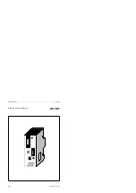
Module Spectrum
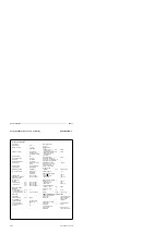
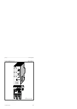
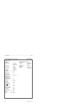
IP 262 Closed-Loop Control Module (continued)
(6ES5 262-8MA12)
(6ES5 262-8MB12)
Binary Outputs of the Open-Loop
Controller (6ES5 262-8MB12)
Number of outputs
8
Galvanic isolation
no
Signal state ”0”
<1.5 V
Signal state ”1”
(L+) - 3.8 V
Maximum load current
100 mA short-circuit
proof
Wiring method
Programmer (PG)
front side via
Operator panel (OP)
15-pin sub D
SINEC-L1 network connection
connector
Connectable are
PG 605, PG 710,
PG
730,
PG 750,
PG 770, OP 393,
OP 395
Analog and binary inputs
front side via
25-pin sub D
connector
Analog and binary outputs
via terminal block of
the bus unit
General data
Input voltage
Rated value
24 V DC
Permissible range
18 to 34 V DC
Permissible range with
the PG 605/OP 393
18 to 27 V DC
Current consumption
Internal (from
the CPU; 9 V)
approx. 20 mA
External (for 24 V;
without load)
approx. 180 mA
External (for 24 V;
without load;
with PG 605 / OP 393)
approx. 340 mA
Ambient temperature
0°
to 55°C
(32 to 131 °F)
EMC Characteristics for Use in S5-95F
Electrostatic discharge
to IEC 801-2
Severity rating: none
tested with
6 kV air discharge
<2 kV contact
discharge
Electromagnetic fields
to IEC 801-3
Severity rating 2
tested with
3 V / m
Fast transient burst
to IEC 801-4
Severity rating 3
tested with
1.2 kV on supply lines
1 kV on signal lines
Technical Specifications
Controller
Total cycle time
(equals scan time)
100 to 200 ms
Resolution of the
open-loop controller
5 ms at 50 Hz
4.2 ms at 60 Hz
Analog Inputs
Number of inputs
4
(suited
for
current,
thermocouple, or
resistance thermo-
meter), voltage with
external switching
Additional input for
reference temperature
1 (resistance
thermometer)
Galvanic isolation
no
Permissible voltage difference
Between inputs
- 1 V to +1 V
Between inputs and
central ground point
- 1 V to +1 V
Digital representation
of the input signal
11 bits+sign
Current input
Input signal range
0 to 20 mA or
4 to 20 mA
Input resistance
24.3
±0.1%
mV Input (for thermocouple)
Input signal range
0 to 50 mV or
- 8.9 to 41.1 mV
(type J, K, L, S)
Cable impedance
30
per wire
Resistance thermometer
Start
18.49
End
219.12
Permissible cable impedance
30
per wire
Binary Inputs
Number of inputs
4
Galvanic isolation
no
Signal state ”0”
- 30 to+4.5 V
or open
Signal state ”1”
+13 to +30 V
(signal state
invertible)
Input resistance
approx. 4 k
Analog Outputs of Constant
Controller (6ES5 262-8MA12)
Number of outputs
3
Galvanic isolation
no
Output signal range
0 to 20 mA or
4 to 20 mA
Maximum permissible load
600
No load voltage
(L+) - 2 V
EWA 4NEB 812 6210-02
A-35


