Error Diagnosis and Elimination
S5-95F
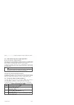
15.3.9 Evaluating the Error Block
You should evaluate the error block entry as soon as the yellow error LED on the base unit goes
on.
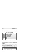
You can evaluate the error in one of two ways:
•
Direct reading out and interpreting of the system event DB
or
•
Using the COM 95F software (refer to the COM 95F manual)
If you have the COM 95F software package, COM 95F interprets the error blocks and provides a
plaintext description of the error.
Note
Please note that some errors occur only in conjunction with other faults or errors which
were duly reported as they occurred. For this reason, always evaluate all reported errors
when doing a complete error/fault analysis.
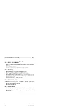
Direct evaluation of the error block is discussed below.
Display the system event DB on the programmer's monitor.
Read out DB254 from the PLC.
Ascertain the number of the last error block stored by viewing DR62.
The 1st DW in the error block is 64 + (error block number times 8).
Determine the error response and the subunit in which the error/fault occurred.
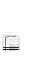
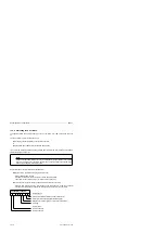
Evaluate byte 0. Determine the error response and the subunit in which the error/fault
occurred. This information is coded in the first byte (byte 0) of the relevant error block.
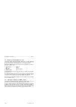
Error flag
Hard STOP (restart possible only after overall reset)
Soft STOP (restart possible after acknowledging)
Response for a signal group as per the DB1 parameters
Error location
Error in subunit B
Error in subunit A
4
3
1
0
Error response
2
7
6
5
First Data Byte (Byte 0)
a a a a a a a a a a a a a a a a a a a a a a a a a a a a a a a a a a a a
a a a a a a a a a a a a a a a a a a a a a a a a a a a a a a a a a a a a
a a a a a a a a a a a a a a a a a a a a a a a a a a a a a a a a a a a a
a a a a a a a a a a a a a a a a a a a a a a a a a a a a a a a a a a a a
a a a a a a a a a a a a a a a a a a a a a a a a a a a a a a a a a a a a
a a a a a a a a a a a a a a a a a a a a a a a a a a a a a a a a a a a a
15-10
EWA 4NEB 812 6210-02


