S5-95F
Interrupt Processing
12.3
Synchronous Interrupt Processing in OB3
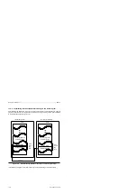
Synchronous interrupt processing means that the signal state change must take place in both
subunits before OB3 is invoked. Execution of OB3 takes place at the same time (i.e. is
synchronous) in both subunits.
All onboard inputs (I 32.0 to I 33.7 and I 59.0 to I 59.3) may also be used as synchronous interrupt
inputs. Those to be used as interrupt inputs must be initialized as such in DB1.
The interrupt inputs must be
•
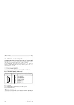
Connected via the 40-pin onboard connector (I 32.0 to I 33.7) and/or the sub D connector
(I 59.0 to I 59.3 and counters A and B),
•
Initialized, and thus enabled, in DB1 and
•
Evaluated in OB3.
Connector Pin Assignments for Interrupt Inputs
See Connector Pin Assignments, section 4.7
Interrupt Triggering
The S5-95F executes interrupt processing routine OB3
•
When an onboard counter reaches the specified comparison value
•
On a) a falling signal edge or b) a rising signal edge or c) on a rising or falling signal edge at an
OB3 interrupt input (the type of signal edge is specified in DB1 using the COM 95F software).
Safety Note
The choice of the interrupt-triggering signal edge is of consequence as regards safety.
Should you decide on edge b) or c), you must prove its safety to the inspector at the
time of the acceptance test.
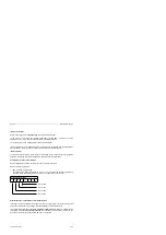
If the appropriate parameters are assigned, the S5-95F responds to a signal edge change at an
interrupt DI as follows:
•
On the falling edge as soon as a signal change from 1 to 0 is detected
in one subunit.
•
On the rising edge when a signal change from 0 to 1 is detected
in both subunits.
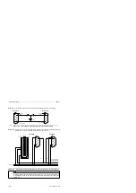
Special Feature of Interrupt DIs with OB1-Oriented Discrepancy Time
In systems with basic units 095-8FA02 you can also use the interrupt DIs with an OB1-oriented
discrepancy time.
To ensure detection of a continuous 1 fault by the S5-95F, the duration of the ”0” and ”1” signal
states must be at least:
parametrized discrepancy time + one OB1 cycle.
EWA 4NEB 812 6210-02
12-9


