Expansion of Basic System with External I/Os
S5-95F
When you have a non-floating configuration, you must make certain that the voltage drop on cables
and does not exceed 1 V.
If 1 V is exceeded, the reference potentials could change and the
modules could malfunction.
!
Warning
If you use non-floating I/O modules, you must provide an external connection between
the chassis ground of the non-floating I/O module and the chassis ground of the CPU.
Example of a Floating Configuration with Digital Modules
Floating configuration is required in the following situations.
•
When you need to increase interference immunity in the load circuits
•
When load circuits cannot be interconnected
•
When you have AC load circuits
If you have a floating configuration, the PLC's control circuit and the load circuit must be galvanically
isolated.
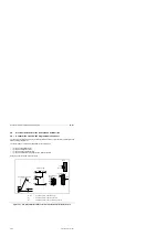
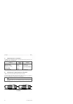
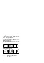
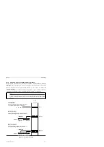
Figure 5-23 shows a simplified connection of galvanically isolated I/Os.
Figure 5-23. Simplified Representation of a Floating, External I/O Connection
1L+
1M
+9 V
Data
GND
•
•
L1
N
a a
a a
a a
a a
•
a a
a a
a a
a a
•
a a
a a
a a
a a
•
a a a
a a a
a a a
a a a
a a a
•
2L+
2M
a a a a a a a a a a a a a a
a a a a a a a a a a a a a a
a a a a a a a a a a a a a a
a a a a a a a a a a a a a a
a a a a a a a a a a a a a a
a a a a a a a a a a a a a a
a a a a a a a a a a a a a a
a a a a a a a a a a a a a a
a a a a a a a a a a a a a a
S5-95F
basic unit
5-26
EWA 4NEB 812 6210-02


