


S5-95F
Analog Value Processing
11
Analog Value Processing
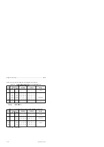
For analog value processing, you can use all analog modules of the S5-100U series. Safety-related
analog value processing is not possible with these modules.
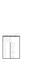
The following sections describe:
•
Connection of sensors and actuators
•
Analog value representation of modules
•
Settings that you must carry out on the modules
•
Examples for using the integrated analog value conversion blocks FB250 and FB 251.
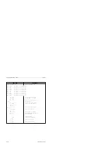
11.1
Analog Input Modules (Type P)
Analog input modules convert analog process signals to digital values that the CPU can process (via
the process image input table, PII). In the following sections, you will find information about the
operating principle, wiring methods, and start-up and programming of analog input modules.
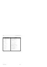
11.2
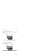
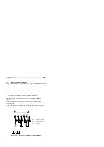
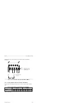
Connecting Current and Voltage Sensors to Analog Input Modules
Observe the following rules to connect current and voltage sensors to analog input modules:
•
When you have multi-channel operations, assign the channels in ascending order. This shortens
the data cycle.
•
Use terminals 1 and 2 for the connection of a compensating box (464-8MA11 ) or for the supply
of two-wire transducers (464-8ME11).
Terminals 1 and 2 cannot be used with the remaining analog input modules.
•
Short-circuit the terminals of unused inputs.
•
Set the reference potentials of the sensors to a common reference potential. Do this to prevent
the potential difference between the common references from exceeding 1 V.
EWA 4NEB 812 6210-02
11-1