


Setting the display mode
To set the required display mode, press the "SELECT/SET" button.
If you do not press the "SELECT/SET" button for longer than 1 minute, the device automatically
changes to display mode A.
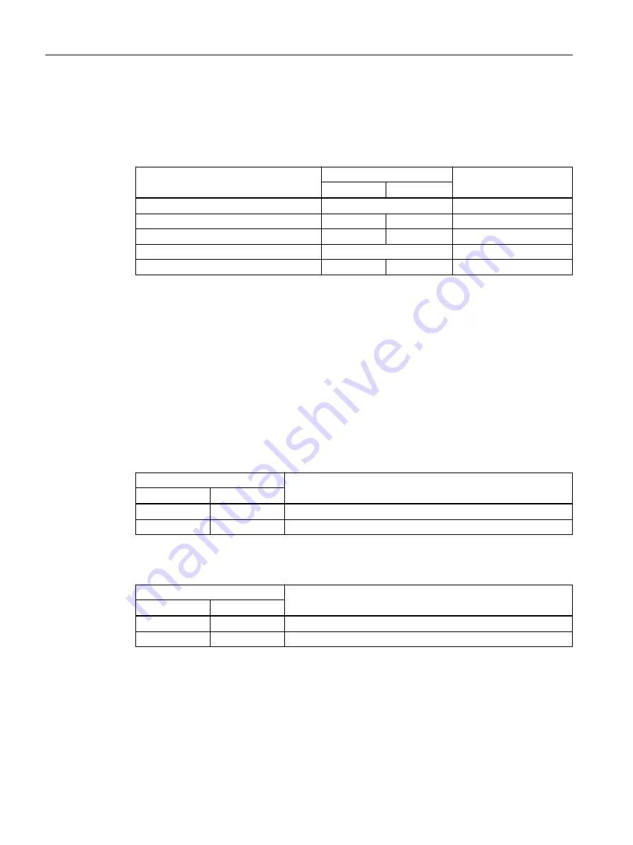
Pressing SELECT/SET button
starting at display mode A
LED status
Display mode
DM1
DM2
-
Off
Display mode A
Press once
On
Off
Display mode B
Press twice
Off
On
Display mode C
Press three times
On
Display mode D
Press four times
Flashing
Off
Display mode E
4.3.6
LEDs "L1" and "L2"
The "L1" and "L2" LEDs indicate the current range of the power supply at connectors L1 and L2.
The meaning of the "L1" and "L2" LEDs depends on the set display mode, see section "LEDs "DM1"
and "DM2" (Page 29)".
Meaning in display modes A, B, C and E
In display modes A, B, C and E, from the "L1" and "L2" LEDs you can see whether the power supply
is higher or lower than a certain voltage limit.
Table 4-1
Power supply with devices with 24 VDC
L1/L2 LEDs
L1/L2 connector
LED color
LED status
-
Off
Power supply too low
Green
On
Power supply is applied
Table 4-2
Power supply with devices with 54 VDC
L1/L2 LEDs
L1/L2 connector
LED color
LED status
-
Off
Power supply too low
Green
On
Power supply is applied
Description of the device
4.3 LED display
SCALANCE XP-200
30
Operating Instructions, 03/2021, C79000-G8976-C428-08
Содержание SCALANCE XP208EEC
Страница 10: ...Safety notices SCALANCE XP 200 10 Operating Instructions 03 2021 C79000 G8976 C428 08 ...
Страница 16: ...Recommendations on network security SCALANCE XP 200 16 Operating Instructions 03 2021 C79000 G8976 C428 08 ...
Страница 52: ...Installation 5 5 Rack mounting SCALANCE XP 200 52 Operating Instructions 03 2021 C79000 G8976 C428 08 ...
Страница 70: ...Connecting up 6 7 Functional ground SCALANCE XP 200 70 Operating Instructions 03 2021 C79000 G8976 C428 08 ...
Страница 88: ...Dimension drawings SCALANCE XP 200 88 Operating Instructions 03 2021 C79000 G8976 C428 08 ...


