

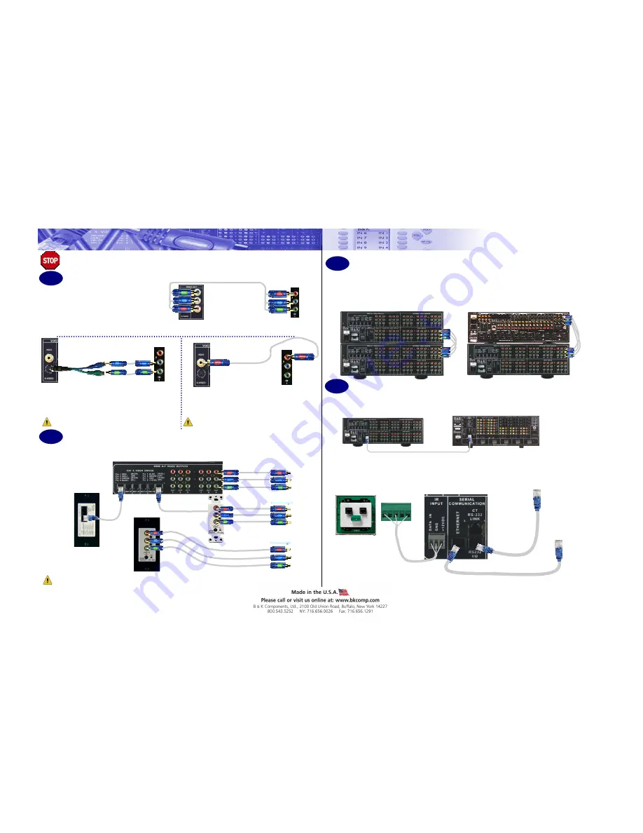
The HD6 takes Composite, S-Video or Compo-
nent Video from the 9 shared video source in-
puts and transcodes the Composite and S-Video
inputs. Connect all sources (Component, S-
Video or Composite) into the Shared or Dedi-
cated Inputs on the HD6.
HD Source
HD6
Warning: Each input can only have ONE connection type.
One input CAN NOT have both composite and S-Video inputs.
Note: If using component video...
Connect the component video sources to the HD6 by the color coded jacks.
Note: If transcoding S-Video…
Connect the S-Video sources by using the supplied
S-Video to RCA adaptor using the blue and green
inputs.
S-Video Source
HD6
Note: If transcoding composite video…
Connect the composite video sources by using the red input.
HD6
Composite Source
Step
1
Warning: Each input can only have ONE connection type.
One input CAN NOT have both composite and S-Video inputs.
HD6 Setup Documentation—HD6Setup
Video Inputs
S-Video Composite
Video
Component Video
HD 6
High Definition Video Switcher
Getting Started
Warning: Do NOT plug the AC power cord into the unit until connections are completed
If needed, the HD6 can be daisy chained for use in up to a 127 Zone System. The HD6 may also be used with a Home
Theater piece. Locate the buffered outputs and connect red , blue and green connections to the corresponding inputs.
To connect two HD6 units, connect the
buffered outputs from the first HD6 to the
Video Inputs of the second HD6.
To connect an HD6 to a home theater piece, connect
the buffered outputs from the HD6 into the component
video inputs on the home theater piece.
Step
2
Back of RCV30 breakout box
Front of RCV30 breakout box
The HD6 outputs video from both the component Zone Line outputs and the CAT-5 output connections simultaneously .
To Television
Connect all outputs to monitors by using the component or RJ45 outputs to RCV30 (P/N 70904) breakout
boxes, which can be used standalone or taken apart to be wall mountable decor.
The RCV30 breakout box taken apart for use
with a wall mount application
Video Outputs
Step
3
Buffered Video Inputs and Outputs
Step
4
When using the HD6 standalone, connect a keypad or IR sensor using the phoenix adaptor for IR control. For use
with serial communication, connect a CAT-5 cable into the RS-232 port. For Network control, connect a straight
CAT-5 cable from a router to the Ethernet port.
OR
Designed to seamlessly integrate with B&K’s CT Series Multi-Zone Receivers, the HD6 operates as a
matched pair to the CT Series receiver. Simply connect a straight CAT-5 cable from the RS-232 output on
the CT Unit to the CT I/O link on the HD6.
Control Connections
+1
2 V
Grou
nd
Da
ta
To RS-232 Device
Controller
Red
Blue
Green
Green
Red
Red
Blue
Green
Red
Blue
Green
Red
Blue
Green
T 568-B Standard
T
568
-B
Stan
da
rd
CT I/O Link
RS-232 I/O
To router for
Network Control
Blue


