


English
English
1. OVERVIEW
1. OVERVIEW
G85139-H1751-U529-D1
G85139-H1751-U529-D1
© Siemens plc 1999
© Siemens plc 1999
4/8/99
4/8/99
88
1.2
1.2 Wiring Guidelines
Wiring Guidelines to Minimise
to Minimise the Effects of
the Effects of EMI
EMI
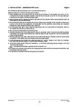
The inverters are designed to operate in an industrial environment where a high level of Electro-Magnetic
The inverters are designed to operate in an industrial environment where a high level of Electro-Magnetic
Interference (EMI) can be expected. Usually, good installation practices will ensure safe and trouble-free
Interference (EMI) can be expected. Usually, good installation practices will ensure safe and trouble-free
operation. If problems are encountered, the following guidelines may prove useful. In particular, grounding of
operation. If problems are encountered, the following guidelines may prove useful. In particular, grounding of
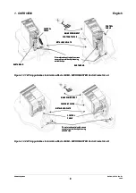
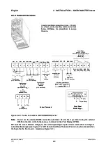
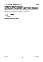
the system at the inverter, as described below, may prove effective. Figures 1.2.1-1.2.3 illustrate how an RFI
the system at the inverter, as described below, may prove effective. Figures 1.2.1-1.2.3 illustrate how an RFI
suppression filter should be installed and connected to the MICROMASTER Vector.
suppression filter should be installed and connected to the MICROMASTER Vector.
(1)
(1)
Ens
Ensure t
ure that
hat all e
all equi
quipme
pment in
nt in the c
the cubi
ubicle i
cle is wel
s well ear
l earthe
thed usi
d using sh
ng short
ort, thi
, thick ea
ck earth
rthing c
ing cabl
able con
e connec
nected t
ted to a
o a
common star point or busbar. It is particularly important that any control equipment that is connected
common star point or busbar. It is particularly important that any control equipment that is connected
to the inverter (such as a PLC) is connected to the same earth or star point as the inverter via a short,
to the inverter (such as a PLC) is connected to the same earth or star point as the inverter via a short,
thick link. Flat conductors (e.g. braids or metal brackets) are preferred as they have lower impedance
thick link. Flat conductors (e.g. braids or metal brackets) are preferred as they have lower impedance
at high frequencies.
at high frequencies.
The return earth from motors controlled by the inverter should be connected directly to the earth
The return earth from motors controlled by the inverter should be connected directly to the earth
connection (PE) on the associated inverter.
connection (PE) on the associated inverter.
(2)
(2)
On
On the
the MID
MIDIMAS
IMASTER
TER Vec
Vector
tor, us
, use sa
e saw-t
w-toot
ooth wa
h washe
shers w
rs when
hen mou
mounti
nting t
ng the i
he inve
nverte
rter an
r and en
d ensur
sure th
e that a
at a
good electrical connection is made between the heatsink and the panel, removing paint if necessary.
good electrical connection is made between the heatsink and the panel, removing paint if necessary.
(3)
(3)
Whe
Wherev
rever po
er possi
ssible
ble, use
, use scr
screen
eened l
ed lead
eads for
s for con
connec
nectio
tions t
ns to the
o the con
contro
trol ci
l circu
rcuitr
itry. Te
y. Termi
rminat
nate the
e the end
ends of
s of
the cable neatly, ensuring that unscreened wires are as short as possible. Use cable glands whenever
the cable neatly, ensuring that unscreened wires are as short as possible. Use cable glands whenever
possible.
possible.
(4)
(4)
Sep
Separa
arate t
te the c
he cont
ontrol
rol cab
cables
les fro
from th
m the po
e power
wer con
connec
nectio
tions a
ns as mu
s much a
ch as po
s possi
ssible
ble, us
, using
ing sep
separat
arate tr
e trunk
unking
ing,,
etc. If control and power cables cross, arrange the cables so that they cross at 90° if possible.
etc. If control and power cables cross, arrange the cables so that they cross at 90° if possible.
(5)
(5)
Ens
Ensure
ure tha
that co
t conta
ntacto
ctors i
rs in th
n the cu
e cubic
bicle a
le are s
re supp
uppres
ressed
sed, ei
, eithe
ther wi
r with R
th R-C s
-C supp
uppres
ressor
sors fo
s for AC
r AC con
contac
tactors
tors
or ‘flywheel’ diodes for DC contactors,
or ‘flywheel’ diodes for DC contactors,
fitted to the coils
fitted to the coils
. Varistor suppressors are also effective. This
. Varistor suppressors are also effective. This
is particularly important if the contactors are controlled from the relay on the inverter.
is particularly important if the contactors are controlled from the relay on the inverter.
(6)
(6)
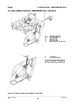
Use
Use scr
screen
eened o
ed or ar
r armour
moured c
ed cable
ables fo
s for th
r the mo
e motor c
tor conn
onnect
ection
ions an
s and gro
d ground
und the
the scr
screen
een at b
at both
oth end
ends vi
s via
a
the cable glands.
the cable glands.
(7)
(7)
If
If the
the drive
drive is
is to
to be
be operated
operated in
in an
an Electro-magnetic
Electro-magnetic noise-sensitive
noise-sensitive environment,
environment, the
the RFI
RFI filter
filter should
should
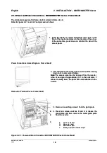
be used to reduce the conducted and radiated interference from the inverter. For optimum
be used to reduce the conducted and radiated interference from the inverter. For optimum
performance, there should be a good conductive bond between filter and metal mounting plate.
performance, there should be a good conductive bond between filter and metal mounting plate.
(8)
(8)
For
For Frame
Frame Size
Size A
A units
units (Fig.1.2.1),
(Fig.1.2.1), the
the flat
flat earth
earth braid
braid strap,
strap, supplied
supplied with
with the
the unit,
unit, should
should be
be fitted
fitted to
to
minimise emissions.
minimise emissions.