


G85139-H1751-U529-D1
G85139-H1751-U529-D1
© Siemens plc 1999
© Siemens plc 1999
4/8/99
4/8/99
4
4
Safety Instructions
Safety Instructions
Before installing and putting this equipment into operation, please read these safety instructions and
Before installing and putting this equipment into operation, please read these safety instructions and
warnings carefully and all the warning signs attached to the equipment. Make sure that the warning
warnings carefully and all the warning signs attached to the equipment. Make sure that the warning
labels are kept in a legible condition and replace missing or damaged labels.
labels are kept in a legible condition and replace missing or damaged labels.
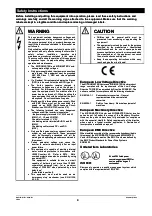
WARNING
WARNING
This equipment contains dangerous voltages and
This equipment contains dangerous voltages and
controls dangerous rotating mechanical parts. Loss o
controls dangerous rotating mechanical parts. Loss o
life, severe personal injury or property damage can
life, severe personal injury or property damage can
result if the instructions contained in this manual are
result if the instructions contained in this manual are
not followed.
not followed.
Only suitable qualified personnel should work on thi
Only suitable qualified personnel should work on thi
equipment, and only after becoming familiar with all
equipment, and only after becoming familiar with all
safety
notices,
installation,
operation
and
safety
notices,
installation,
operation
and
maintenance procedures contained in this manual.
maintenance procedures contained in this manual.
The successful and safe operation of this equipment
The successful and safe operation of this equipment
is dependent upon its proper handling, installation,
is dependent upon its proper handling, installation,
operation and maintenance.
operation and maintenance.
••
The
The MICROMASTER
MICROMASTER and
and MIDIMASTER
MIDIMASTER Vecto
Vecto
units operate at high voltages.
units operate at high voltages.
••
Only
Only permanently-w
permanently-wired
ired input
input power
power connections
connections
are allowed. This equipment must be grounded
are allowed. This equipment must be grounded
(IEC 536 Class 1, NEC and other applicable
(IEC 536 Class 1, NEC and other applicable
standards).
standards).
••
If
If a
a Residual
Residual Current-operate
Current-operated
d protective
protective Device
Device
(RCD) is to be used it must be an RCD type B.
(RCD) is to be used it must be an RCD type B.
••
The dc-link capaci
The dc-link capacitor remains charged to
tor remains charged to
dangerous voltages even when the power i
dangerous voltages even when the power i
removed. For this reason it is not permissible to
removed. For this reason it is not permissible to
open the equipment until five minutes after the
open the equipment until five minutes after the
power has been turned off. When handling the
power has been turned off. When handling the
open equipment it should be noted that live part
open equipment it should be noted that live part
are exposed. Do not touch these
are exposed. Do not touch these live parts.
live parts.
••
Machines
Machines with
with a thr
a three pha
ee phase po
se power
wer supply,
supply, fitted
fitted
with EMC filters, must not be connected to a
with EMC filters, must not be connected to a
supply via an ELCB (Earth Leakage Circuit-
supply via an ELCB (Earth Leakage Circuit-
Breaker -
Breaker -
see DIN VDE 0160, section 6.5).
see DIN VDE 0160, section 6.5).
••
The follow
The following termi
ing terminals can
nals can carry da
carry dangerous
ngerous
voltages even if the
voltages even if the inverter is inoperative:
inverter is inoperative:
- the power supply terminals L/L1, N/L2 and
- the power supply terminals L/L1, N/L2 and L3
L3
(MMV) - L1, L2, and L3 (MDV).
(MMV) - L1, L2, and L3 (MDV).
-the motor terminals U, V, W.
-the motor terminals U, V, W.
-the braking resistor terminals B+/DC+ and B-
-the braking resistor terminals B+/DC+ and B-
(MMV).
(MMV).
-the braking unit terminals DC+ and DC-
-the braking unit terminals DC+ and DC-
(MDV).
(MDV).
••
Only
Only qualified
qualified personnel
personnel may c
may connect,
onnect, start
start the
the
system up and repair faults. These personnel
system up and repair faults. These personnel
must be thoroughly acquainted with all the
must be thoroughly acquainted with all the
warnings and operating procedures contained in
warnings and operating procedures contained in
this manual.
this manual.
••
Certain parameter
Certain parameter settings may c
settings may cause the
ause the
inverter to restart automatically after an input
inverter to restart automatically after an input
power failure.
power failure.
••
This
This equipment
equipment is c
is capable of
apable of providing
providing internal
internal
motor overload protection in accordance with
motor overload protection in accordance with
UL508C
UL508C section
section 42.
42.
Refer
Refer to
to P074.
P074.
Moto
Moto
overload protection can also be provided by
overload protection can also be provided by using
using
an external PTC.
an external PTC.
This equipment is suitable for use in a circuit
This equipment is suitable for use in a circuit
capable of delivering not more than 100,000
capable of delivering not more than 100,000
symmetrical amperes (rms), for a maximum
symmetrical amperes (rms), for a maximum
voltage of 230/460V* when protected by a time
voltage of 230/460V* when protected by a time
delay fuse*.
delay fuse*.
*As detailed in section 8.
*As detailed in section 8.
••
This
This equipment
equipment must
must
not
not
be used as an
be used as an
‘emergency stop’ mechanism
‘emergency stop’ mechanism
(see EN 60204,
(see EN 60204,
9.2.5.4).
9.2.5.4).
CAUTION
CAUTION
••
Children and the general
Children and the general public must be
public must be
prevented from accessing or approaching the
prevented from accessing or approaching the
equipment!
equipment!
••
This
This equipment
equipment must
must only
only be
be used
used for
for the
the purpose
purpose
specified by the manufacturer. Unauthorised
specified by the manufacturer. Unauthorised
modifications and the use of spare parts and
modifications and the use of spare parts and
accessories that are not sold or recommended by
accessories that are not sold or recommended by
the manufacturer of the equipment can cause
the manufacturer of the equipment can cause
fires, electric shocks and injuries.
fires, electric shocks and injuries.
••
Keep these
Keep these operating
operating instructions
instructions within e
within easy
asy
reach and give them to all users!
reach and give them to all users!
European Low Voltage Directive
European Low Voltage Directive
The MICROMASTER Vector and MIDIMASTER Vector product
The MICROMASTER Vector and MIDIMASTER Vector product
range complies with the requirements of the Low Voltage
range complies with the requirements of the Low Voltage
Directive 73/23/EEC as amended by Directive 93/68/EEC. The
Directive 73/23/EEC as amended by Directive 93/68/EEC. The
units are certified for compliance with the following standards:
units are certified for compliance with the following standards:
EN
EN 601
60146-
46-1-
1-1
1
Sem
Semico
icondu
nducto
ctor c
r conv
onvert
erters
ers - G
- Gene
eneral
ral
requirements and line commutated
requirements and line commutated
converters
converters
EN
EN 60
6020
204-
4-1
1
Sa
Safe
fety
ty of
of ma
mach
chin
iner
ery -
y - El
Elec
ectr
tric
ical
al eq
equi
uipm
pmen
ent o
t of f
machines
machines
European Machinery Directive
European Machinery Directive
The MICROMASTER Vector and MIDIMASTER Vector inverter
The MICROMASTER Vector and MIDIMASTER Vector inverter
series do not fall under the scope of the Machinery Directive.
series do not fall under the scope of the Machinery Directive.
However, the products have been fully evaluated for compliance
However, the products have been fully evaluated for compliance
with the essential Health & Safety requirements of the directive
with the essential Health & Safety requirements of the directive
when used in a typical machine application. A Declaration of
when used in a typical machine application. A Declaration of
Incorporation is available on request.
Incorporation is available on request.
European EMC Directive
European EMC Directive
When installed according to the
When installed according to the recommendations described in
recommendations described in
this manual, the
this manual, the MICROMASTER Vector and MIDIMASTER
MICROMASTER Vector and MIDIMASTER
Vector fulfil all requirements of the EMC Directive as defined by
Vector fulfil all requirements of the EMC Directive as defined by
the EMC Product Standard for Power Drive Systems
the EMC Product Standard for Power Drive Systems
EN61800-3.
EN61800-3.
Underwriters Laboratories
Underwriters Laboratories
ISO 9001
ISO 9001
Siemens plc operates a quality management system, which
Siemens plc operates a quality management system, which
complies with the requirements of ISO 9001.
complies with the requirements of ISO 9001.
UL and CUL listed power
UL and CUL listed power
conversion equipment 5B33 for
conversion equipment 5B33 for
use in a pollution degree 2
use in a pollution degree 2
environment
environment