


2
2.
. IIN
NS
ST
TA
AL
LL
LA
AT
TIIO
ON
N –
– M
MIIC
CR
RO
OM
MA
AS
ST
TE
ER
R V
Ve
ec
ctto
orr
E
En
ng
glliis
sh
h
© Siemens plc 1999
© Siemens plc 1999
G85139-H1751-U529-D1
G85139-H1751-U529-D1
23
23
4/8/99
4/8/99
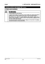
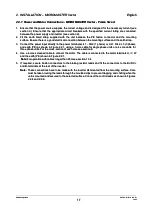
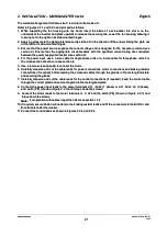
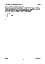
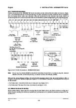
2.2.5 External Motor Thermal Overload Protection
2.2.5 External Motor Thermal Overload Protection
When operated below rated speed, the cooling effect of fans fitted to the motor shaft is reduced. so that most
When operated below rated speed, the cooling effect of fans fitted to the motor shaft is reduced. so that most
motors require de-rating for continuous operation at low frequencies. To ensure that motors are protected
motors require de-rating for continuous operation at low frequencies. To ensure that motors are protected
against overheating under these conditions it is strongly recommended that a PTC temperature sensor is fitted
against overheating under these conditions it is strongly recommended that a PTC temperature sensor is fitted
to the motor and connected to the inverter control terminals as shown in Figure 2.2.5.
to the motor and connected to the inverter control terminals as shown in Figure 2.2.5.
Note:
Note:
To enable the motor overload protection trip function, set parameter P087=1
To enable the motor overload protection trip function, set parameter P087=1
MOTOR
MOTOR
PT
PTC
C
14
14
15
15
Inverter Control
Inverter Control
Terminals
Terminals
Figure 2.2.5: Motor Overload PTC Connection.
Figure 2.2.5: Motor Overload PTC Connection.