


3
3.
. IIN
NS
ST
TA
AL
LL
LA
AT
TIIO
ON
N
–
–
M
MIID
DIIM
MA
AS
ST
TE
ER
R
V
Ve
ec
ctto
orr
E
En
ng
glliis
sh
h
© Siemens plc 1999
© Siemens plc 1999
G85139-H1751-U529-D1
G85139-H1751-U529-D1
29
29
4/8/99
4/8/99
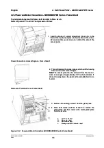
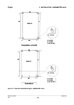
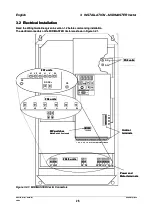
To gain access to the power and control terminals:
To gain access to the power and control terminals:
••
Frame size 4, 5 :
Frame size 4, 5 :
remove the four M4 screws from the front cover and remove the cover from the inverter.
remove the four M4 screws from the front cover and remove the cover from the inverter.
••
Frame size 6:
Frame size 6:
remove the six M4 screws
remove the six M4 screws from the front cover and remove the c
from the front cover and remove the cover from the inverter.
over from the inverter.
••
Frame size 7:
Frame size 7:
remove the four M4 screws from the lower front cover and remove the lower front cover from
remove the four M4 screws from the lower front cover and remove the lower front cover from
the inverter.
the inverter.
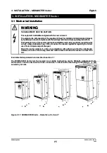
WARNING
WARNING
Ensure that the motor is configured for the correct supply voltage.
Ensure that the motor is configured for the correct supply voltage.
Make sure that the input power supply is isolated before making or changing any connections.
Make sure that the input power supply is isolated before making or changing any connections.
When synchronous machines are connected or when coupling several motors in parallel, the
When synchronous machines are connected or when coupling several motors in parallel, the
inverter must be operated with voltage/frequency control characteristic (P077= 0 or 2) and slip
inverter must be operated with voltage/frequency control characteristic (P077= 0 or 2) and slip
compensation must be disabled (P071 = 0).
compensation must be disabled (P071 = 0).
CAUTION
CAUTION
The control, power supply and motor leads
The control, power supply and motor leads
must
must
be laid separately. They must
be laid separately. They must
not
not
be fed
be fed
through the same cable conduit/trunking.
through the same cable conduit/trunking.
High voltage insulation test equipment must
High voltage insulation test equipment must
not
not
be used on cables connected to the inverter.
be used on cables connected to the inverter.
Use screened cable for the control cable, Class 1 60/75
Use screened cable for the control cable, Class 1 60/75
o
o
C copper wire only.
C copper wire only.
Feed the cables through the correct glands in the base of the inverter. Secure the cable glands to the inverter
Feed the cables through the correct glands in the base of the inverter. Secure the cable glands to the inverter
and connect the leads to the power, motor and control terminals in accordance with the information supplied in
and connect the leads to the power, motor and control terminals in accordance with the information supplied in
sections 3.2.1 and 3.2.2. Ensure that the leads are connected correctly and the equipment is properly earthed.
sections 3.2.1 and 3.2.2. Ensure that the leads are connected correctly and the equipment is properly earthed.
Frame size 4 and 5:
Frame size 4 and 5:
Tighten up each of the power and motor terminal screws to 1.1 Nm
Tighten up each of the power and motor terminal screws to 1.1 Nm
..
Frame size 6:
Frame size 6:
Tighten up each of the power and motor terminal Allen-screws to 3.0 Nm
Tighten up each of the power and motor terminal Allen-screws to 3.0 Nm
..
Frame size 7:
Frame size 7:
Tighten up each of the M12 power and motor terminal nuts to 30 Nm.
Tighten up each of the M12 power and motor terminal nuts to 30 Nm.
Secure the front cover to the inverter when all connections are complete.
Secure the front cover to the inverter when all connections are complete.
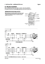
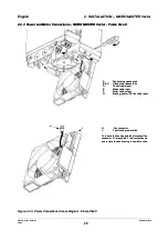
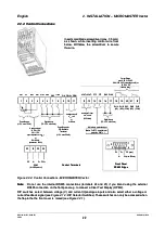
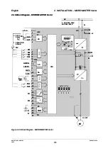
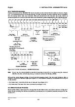
3.2.1
3.2.1 Power a
Power and Motor
nd Motor Connections
Connections
1.
1. Ensure that the pow
Ensure that the power source supplies
er source supplies the correct voltage
the correct voltage and the necessary
and the necessary current.
current. Ensure that the
Ensure that the
appropriate circuit-breaker or fuses with the specified current rating are connected between the power
appropriate circuit-breaker or fuses with the specified current rating are connected between the power
supply and inverter
supply and inverter
(see section 8)
(see section 8)
..
2.
2. Connect the pow
Connect the power input to
er input to the power termi
the power terminals L1, L2,
nals L1, L2, L3 (3 phase)
L3 (3 phase) and
and earth (PE) (
earth (PE) (
shown in Figure 3.2.1
shown in Figure 3.2.1
))
using a 4-core cable and lugs to suit the cable size. For the cross-section of each core, see section 8.
using a 4-core cable and lugs to suit the cable size. For the cross-section of each core, see section 8.
3.
3. Use a 4-core screened cable and suitable lugs to connect the motor leads to the motor terminals U, V, W
Use a 4-core screened cable and suitable lugs to connect the motor leads to the motor terminals U, V, W
and earth (PE) (
and earth (PE) (
shown in Figure 3.2.1
shown in Figure 3.2.1
).
).
Note:
Note:
For operation with cables longer than 25m see section 1.3.4
For operation with cables longer than 25m see section 1.3.4
4.
4. If required, connect the braking
If required, connect the braking unit leads to the DC
unit leads to the DC- and DC+ terminals.
- and DC+ terminals.
5.
5. Tighten all
Tighten all the power
the power and motor
and motor terminals.
terminals.
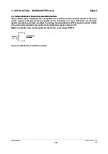
Asynchronous
Asynchronous and
and synchronous
synchronous motors
motors can
can be
be connected
connected to
to the
the MIDIMASTER
MIDIMASTER Vector
Vector inverters
inverters either
either
individually or in parallel.
individually or in parallel.
Note
Note
:
: If a synchronous
If a synchronous motor is connected
motor is connected to the inverter,
to the inverter, the motor current
the motor current may be two
may be two and a half
and a half to three
to three
times greater than that expected so the inverter must be de-rated accordingly.
times greater than that expected so the inverter must be de-rated accordingly.