


3
3.
. IIN
NS
ST
TA
AL
LL
LA
AT
TIIO
ON
N
–
–
M
MIID
DIIM
MA
AS
ST
TE
ER
R
V
Ve
ec
ctto
orr
E
En
ng
glliis
sh
h
© Siemens plc 1999
© Siemens plc 1999
G85139-H1751-U529-D1
G85139-H1751-U529-D1
27
27
4/8/99
4/8/99
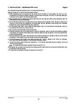
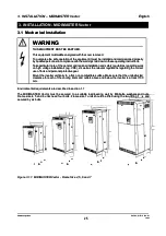
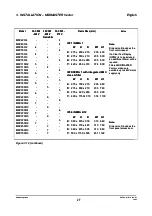
M
Mo
od
deell
3
3 A
AC
C 220088
- 240 V
- 240 V
3AC 380
3AC 380
-500 V
-500 V
3 AC 525 -
3 AC 525 -
575 V
575 V
Frame Sizes ( mm)
Frame Sizes ( mm)
Notes
Notes
Frame Size
Frame Size
MDV220/4
MDV220/4
MDV400/4
MDV400/4
MDV550/2
MDV550/2
MDV550/4
MDV550/4
MDV750/2
MDV750/2
MDV750/3
MDV750/3
MDV750/4
MDV750/4
MDV1100/2
MDV1100/2
MDV1100/3
MDV1100/3
MDV1100/4
MDV1100/4
MDV1500/2
MDV1500/2
MDV1500/3
MDV1500/3
MDV1500/4
MDV1500/4
MDV1850/2
MDV1850/2
MDV1850/3
MDV1850/3
MDV1850/4
MDV1850/4
MDV2200/2
MDV2200/2
MDV2200/3
MDV2200/3
MDV2200/4
MDV2200/4
MDV3000/2
MDV3000/2
MDV3000/3
MDV3000/3
MDV3000/4
MDV3000/4
MDV3700/2
MDV3700/2
MDV3700/3
MDV3700/3
MDV3700/4
MDV3700/4
MDV4500/2
MDV4500/2
MDV4500/3
MDV4500/3
MDV5500/3
MDV5500/3
MDV7500/3
MDV7500/3
--
--
4
4
--
4
4
--
--
5
5
--
--
6
6
--
--
6
6
--
--
6
6
--
--
7
7
--
--
7
7
--
--
7
7
--
--
--
--
--
--
--
--
4
4
--
--
4
4
--
--
5
5
--
--
5
5
--
--
6
6
--
--
6
6
--
--
6
6
--
--
7
7
7
7
7
7
4
4
4
4
--
4
4
--
--
4
4
--
--
4
4
--
--
5
5
--
--
5
5
--
--
6
6
--
--
6
6
--
--
6
6
--
--
--
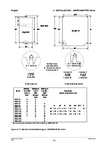
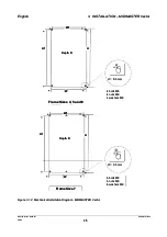
IP21 / NEMA 1
IP21 / NEMA 1
W
W
H
H
D
D
W
W1
1
H
H1
1
4
4
=
= 27
275
5 x 4
x 450
50 x
x 21
210
0
23
235
5 43
430
0
5
5
=
= 2
27
75
5 x
x 5
55
50
0 x
x 2
21
10
0
2
23
35
5 5
53
30
0
6
6
=
= 2
27
75
5 x
x 6
65
50
0 x
x 2
28
85
5
2
23
35
5 6
63
30
0
7
7
=
= 4
42
20
0 x
x 8
85
50
0 x
x 3
31
10
0
3
37
74
4 8
83
30
0
IP20/NEMA 1 with integrated EMC
IP20/NEMA 1 with integrated EMC
class A filter
class A filter
W
W
H
H
D
D
W
W1
1
H
H1
1
4
4
=
= 27
275
5 x 7
x 700
00 x
x 21
210
0
23
235
5 68
680
0
5
5
=
= 2
27
75
5 x
x 8
80
00
0 x
x 2
21
10
0
2
23
35
5 7
78
80
0
6
6
=
= 2
27
75
5 x
x 9
92
20
0 x
x 2
28
85
5
2
23
35
5 9
90
00
0
7
7
=
= 42
420
0 x
x 11
115
50x
0x 31
310
0
37
374
4 11
1130
30
IP56 / NEMA 4/12
IP56 / NEMA 4/12
W
W
H
H
D
D
W
W1
1
H
H1
1
4
4
=
= 36
360
0 x 6
x 675
75 x
x 37
376
6
31
313
3 64
649
9
5
5
=
= 3
36
60
0 x
x 7
77
75
5 x
x 4
44
45
5
3
31
13
3 7
74
49
9
6
6
=
= 3
36
60
0 x
x 8
87
75
5 x
x 5
50
05
5
3
31
13
3 8
84
49
9
7
7
= 500
= 500 x
x 1150
1150 x
x 595
595
451 1122
451 1122
Note:
Note:
Dimension D includes the
Dimension D includes the
front control panel.
front control panel.
If a Clear Text Display
If a Clear Text Display
(OPM2) is to be included,
(OPM2) is to be included,
an additional 30mm will be
an additional 30mm will be
required.
required.
Filtered
Filtered MIDIMASTE
MIDIMASTER
R
Vector versions are
Vector versions are
available up to 460V mains
available up to 460V mains
supply only.
supply only.
Note:
Note:
Dimension D includes the
Dimension D includes the
front panel access door.
front panel access door.
Figure: 3.1.2 (continued)
Figure: 3.1.2 (continued)