


2
2.
. IIN
NS
ST
TA
AL
LL
LA
AT
TIIO
ON
N –
– M
MIIC
CR
RO
OM
MA
AS
ST
TE
ER
R V
Ve
ec
ctto
orr
E
En
ng
glliis
sh
h
© Siemens plc 1999
© Siemens plc 1999
G85139-H1751-U529-D1
G85139-H1751-U529-D1
21
21
4/8/99
4/8/99
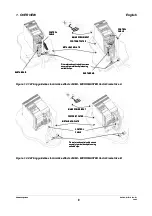
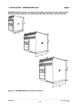
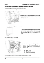
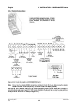
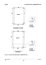
The terminal arrangement for frame size C is similar to frame size A
The terminal arrangement for frame size C is similar to frame size A
..
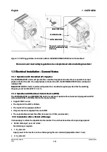
Refer to Figures 2.2.1 and 2.2.3 and proceed as follows:
Refer to Figures 2.2.1 and 2.2.3 and proceed as follows:
1. While supporting the fan housing with one hand, insert the blade of a screwdriver into slot A on the
1. While supporting the fan housing with one hand, insert the blade of a screwdriver into slot A on the
underside of the inverter and press upwards to release the securing tab. Lower the fan housing, allowing it
underside of the inverter and press upwards to release the securing tab. Lower the fan housing, allowing it
to swing out to the right on its side-mounted hinges.
to swing out to the right on its side-mounted hinges.
2.
2. Applying pressure to the gland plate release clips B and C in the direc
Applying pressure to the gland plate release clips B and C in the direction of the arrows. Swing the plate out
tion of the arrows. Swing the plate out
to the left on its side-mounted hinges.
to the left on its side-mounted hinges.
3.
3. Ensure that the power source supplies the correc
Ensure that the power source supplies the correct voltage and is designed for the necessary
t voltage and is designed for the necessary current
current
(see
(see
section 8)
section 8)
. Ensure that the appropriate circuit-breakers with the specified current rating are connected
. Ensure that the appropriate circuit-breakers with the specified current rating are connected
between the power supply and inverter
between the power supply and inverter
(see section 8)
(see section 8)
..
4.
4. For the power input, use a 3-core cable
For the power input, use a 3-core cable for single phase units or a 4-core c
for single phase units or a 4-core cable for three phase units. For
able for three phase units. For
the cross-section of each core see section 8.
the cross-section of each core see section 8.
5.
5. Use a 4-core
Use a 4-core screened cable to
screened cable to connect the motor.
connect the motor.
6.
6. Carefully measure and cut the cable
Carefully measure and cut the cable leads for power connections, motor connections
leads for power connections, motor connections and braking resistor
and braking resistor
connections (if required) before feeding the screened cables through the glands in the metal gland plate
connections (if required) before feeding the screened cables through the glands in the metal gland plate
and securing the glands.
and securing the glands.
7.
7. Carefully measure and cut the cable leads for the control connec
Carefully measure and cut the cable leads for the control connections (if required). Feed the control cable
tions (if required). Feed the control cable
through the correct gland and secure the gland to the metal gland-plate.
through the correct gland and secure the gland to the metal gland-plate.
8.
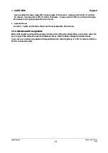
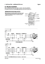
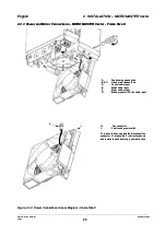
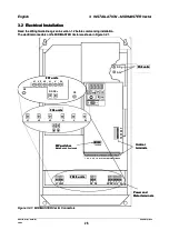
8. Connect the power input leads to the power termin
Connect the power input leads to the power terminals L/L1 - N/L2 (1 phase) or L/L1, N/L2, L3 (3 phase),
als L/L1 - N/L2 (1 phase) or L/L1, N/L2, L3 (3 phase),
and
and earth
earth (PE)
(PE) ((
shown in Figure 2.2.1
shown in Figure 2.2.1
) and torque down the screws.
) and torque down the screws.
9.
9. Connect the motor leads
Connect the motor leads to the motor terminals U,
to the motor terminals U, V, W and the earth (PE) (
V, W and the earth (PE) (
shown in Figure 2.2.1
shown in Figure 2.2.1
) and
) and
torque down the screws.
torque down the screws.
Note:
Note:
For operation with cables longer than 25m see section 1.3.4
For operation with cables longer than 25m see section 1.3.4
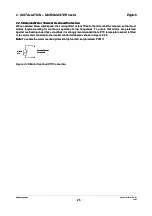
10.If required, secure Faston connectors to the
10.If required, secure Faston connectors to the braking resistor leads and fit the
braking resistor leads and fit the connectors to the B+/DC+ and
connectors to the B+/DC+ and
B- terminals under the inverter.
B- terminals under the inverter.
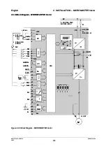
11.Connect the control leads as shown in Figures 2.2.4 and 2.2.6
11.Connect the control leads as shown in Figures 2.2.4 and 2.2.6