Siemens MICROMASTER Vector MMV110 Скачать руководство пользователя страница 6

English

English

1.  OVERVIEW 

1.  OVERVIEW 

G85139-H1751-U529-D1

G85139-H1751-U529-D1

© Siemens plc 1999

© Siemens plc 1999

4/8/99

4/8/99

6

6

1.  OVERVIEW

1.  OVERVIEW

The MICROMASTER Vector (MMV) and MIDIMASTER Vector (MDV) are a standard range of inverters with

The MICROMASTER Vector (MMV) and MIDIMASTER Vector (MDV) are a standard range of inverters with
sensorless  vector 

sensorless  vector  capability  suitable 

capability  suitable  for  controlling  the 

for  controlling  the  speed  of  3 

speed  of  3  phase  motors. 

phase  motors.  Various  models 

Various  models  are

are

available, ranging from the compact 120 W MICROMASTER Vector up to the 75 kW MIDIMASTER Vector.

available, ranging from the compact 120 W MICROMASTER Vector up to the 75 kW MIDIMASTER Vector.

Sensorless vector control allows the inverter to calculate the changes required in output current and frequency

Sensorless vector control allows the inverter to calculate the changes required in output current and frequency
in order to maintain the desired motor speed across a wide range of load conditions.

in order to maintain the desired motor speed across a wide range of load conditions.

For additional product information such as application examples, part numbers, operation with long cables etc,

For additional product information such as application examples, part numbers, operation with long cables etc,
please refer to catalog DA64 or to

please refer to catalog DA64 or to

http://www.con.siemens.co.uk

http://www.con.siemens.co.uk

Features:

Features:

••

Easy 

Easy to 

to install, 

install, program 

program and 

and commission.

commission.

••

Overload 

Overload capability 

capability 200% 

200% for 

for 3s 

3s followed 

followed by 

by 150% 

150% for 

for 60s.

60s.

••

High 

High starting 

starting torque 

torque and 

and accurate 

accurate motor 

motor speed 

speed regulation 

regulation by 

by vector 

vector control.

control.

••

Optional i

Optional integrated RFI 

ntegrated RFI filter on 

filter on single-phase 

single-phase input inv

input inverters MMV12 

erters MMV12 - MMV 

- MMV 300, and 

300, and three phase 

three phase input

input

inverters MMV220/3 to MMD750/3

inverters MMV220/3 to MMD750/3

••

Fast 

Fast Current 

Current Limit 

Limit (FCL) 

(FCL) for 

for reliable 

reliable trip-free 

trip-free operation.

operation.

••

0 to 

to 50

50

°°

C temperature range (0 to 40

C temperature range (0 to 40

°°

C for MIDIMASTER Vector)

C for MIDIMASTER Vector)

••

Closed lo

Closed loop process 

op process control using 

control using a standard 

a standard Proportional, Integ

Proportional, Integral, Derivativ

ral, Derivative (PID) 

e (PID) control loop 

control loop function.

function.

15 V, 50 mA supply provided for feedback transducer.

15 V, 50 mA supply provided for feedback transducer.

••

Remote control 

Remote control capability 

capability via RS485 

via RS485 serial li

serial link using 

nk using the USS 

the USS protocol w

protocol with the 

ith the ability to 

ability to control up 

control up to 31

to 31

inverters via the USS protocol.

inverters via the USS protocol.

••

Factory 

Factory default 

default parameter 

parameter settings 

settings pre-programmed 

pre-programmed for 

for European, 

European, Asian 

Asian and 

and North 

North American

American

requirements.

requirements.

••

Output 

Output frequency 

frequency (and 

(and hence 

hence motor 

motor speed) 

speed) can 

can be 

be controlled 

controlled by:

by:

(1) 

(1)  Frequency setp

Frequency setpoint using 

oint using the keypad.

the keypad.

(2) 

(2)  High resolution analogu

High resolution analogue setpoint (voltage or 

e setpoint (voltage or current input).

current input).

(3) 

(3)  External potentiometer 

External potentiometer to control 

to control motor speed.

motor speed.

(4) 

(4)  8 fixed 

8 fixed frequencies via 

frequencies via binary inputs.

binary inputs.

(5) 

(5)  Motorised 

Motorised potentiometer 

potentiometer function.

function.

(6) 

(6)  Serial 

Serial interface.

interface.

••

Built-in 

Built-in DC 

DC injection 

injection brake 

brake with 

with special 

special COMPOUND 

COMPOUND BRAKING.

BRAKING.

••

Built-in 

Built-in brake 

brake chopper 

chopper for 

for external 

external resistor 

resistor (MMV).

(MMV).

••

Acceleration/deceleration 

Acceleration/deceleration times 

times with 

with programmable 

programmable smoothing.

smoothing.

••

Two 

Two fully-programmable 

fully-programmable relay 

relay outputs 

outputs (13 

(13 functions).

functions).

••

Fully-programmable 

Fully-programmable analogue 

analogue outputs 

outputs (1 

(1 for 

for MMV, 

MMV, 2 

2 for 

for MDV).

MDV).

••

External  Opti

External  Options  connec

ons  connector  for 

tor  for optional 

optional multi-language 

multi-language  Clear 

Clear Text  D

Text  Display 

isplay (OPM2),  optional 

(OPM2),  optional PROFIBUS-

PROFIBUS-

DP module or CANbus module

DP module or CANbus module

••

Dual 

Dual motor-parameter 

motor-parameter sets 

sets available 

available if 

if Clear 

Clear Text 

Text Display 

Display (OPM2) 

(OPM2) fitted.

fitted.

••

Automatic 

Automatic recognition 

recognition of 

of 2,4,6 

2,4,6 or 

or 8-pole 

8-pole motors 

motors by 

by software.

software.

••

Integral 

Integral software 

software controlled 

controlled cooling 

cooling fan.

fan.

••

Side-by-side 

Side-by-side mounting 

mounting without 

without additional 

additional clearance.

clearance.

••

Optional 

Optional protection 

protection to 

to IP56 

IP56 (NEMA 

(NEMA 4/12) 

4/12) for 

for MIDIMASTER 

MIDIMASTER Vector 

Vector inverters.

inverters.

Содержание MICROMASTER Vector MMV110

Страница 1: ...ION MIDIMASTER MIDIMASTER Vector Vector 25 25 4 4 CONTROLS CONTROLS AND AND BASIC BASIC OPERATION OPERATION 32 32 5 5 OPERATING OPERATING MODES 36 MODES 36 6 6 SYSTEM SYSTEM PARAMETERS PARAMETERS 41 41 7 7 FAULT FAULT AND AND WARNING WARNING CODES 65 CODES 65 8 8 SPECIFICATIONS SPECIFICATIONS 67 67 9 9 SUPPLEMENTARY SUPPLEMENTARY INFORMATION 73 INFORMATION 73 MICROMASTER MICROMASTER Vector Vector ...

Страница 2: ...23 3 2 2 2 2 6 6 B Bl lo oc ck k D Di ia ag gr ra am m M MI IC CR RO OM MA AS ST TE ER R V Ve ec ct to or r 2 24 4 3 3 I In ns st ta al ll la at ti io on n M MI ID DI IM MA AS ST TE ER R V Ve ec ct to or r 25 25 3 3 1 1 M Me ec ch ha an ni ic ca al l I In ns st ta al ll la at ti io on n 2 25 5 3 3 2 2 E El le ec ct tr ri ic ca al l I In ns st ta al ll la at ti io on n 2 28 8 3 3 2 2 1 1 P Po ow we...

Страница 3: ...7 7 F Fa au ul lt t a an nd d W Wa ar rn ni in ng g C Co od de es s 65 65 7 7 1 1 F Fa au ul lt t C Co od de es s 6 65 5 7 7 2 2 W Wa ar rn ni in ng g C Co od de es s 6 66 6 8 8 S Sp pe ec ci if fi ic ca at ti io on ns s 67 67 9 9 S Su up pp pl le em me en nt ta ar ry y I In nf fo or rm ma at ti io on n 73 73 9 9 1 1 A Ap pp pl li ic ca at ti io on n E Ex xa am mp pl le e 7 73 3 9 9 2 2 U US SS S ...

Страница 4: ... the inverter to restart automatically after an input inverter to restart automatically after an input power failure power failure This This equipment equipment is c is capable of apable of providing providing internal internal motor overload protection in accordance with motor overload protection in accordance with UL508C UL508C section section 42 42 Refer Refer to to P074 P074 Moto Moto overload...

Страница 5: ...minal current current The The motor motor data data parameters parameters must must be be accurately accurately entered entered P080 P085 and P080 P085 and an an auto auto calibration performed P088 1 calibration performed P088 1 before the motor before the motor is started is started Unstable unpredictable Unstable unpredictable motor operation eg reverse rotation may result if this is not done m...

Страница 6: ...rivativ ral Derivative PID e PID control loop control loop function function 15 V 50 mA supply provided for feedback transducer 15 V 50 mA supply provided for feedback transducer Remote control Remote control capability capability via RS485 via RS485 serial li serial link using nk using the USS the USS protocol w protocol with the ith the ability to ability to control up control up to 31 to 31 inv...

Страница 7: ...Do not install the water hazards e g Do not install the inverter beneath inverter beneath pipes that are subject to pipes that are subject to condensation Avoid installing condensation Avoid installing the inverter where excessive humidity and the inverter where excessive humidity and condensation may occur condensation may occur Ensure that the inverter s air vents are not obstructed Ensure that ...

Страница 8: ...r an r and en d ensur sure th e that a at a good electrical connection is made between the heatsink and the panel removing paint if necessary good electrical connection is made between the heatsink and the panel removing paint if necessary 3 3 Whe Wherev rever po er possi ssible ble use use scr screen eened l ed lead eads for s for con connec nectio tions t ns to the o the con contro trol ci l cir...

Страница 9: ...Frame Size B MAINS POWER INPUT MAINS POWER INPUT METAL BACK PLATE METAL BACK PLATE FOOTPRINT FILTER FOOTPRINT FILTER CONTROL CONTROL CABLE CABLE CONTROL CONTROL CABLE CABLE Fix motor and control cable screens Fix motor and control cable screens securely to metal back plate using securely to metal back plate using suitable clips suitable clips EARTH BRAID EARTH BRAID EARTH BRAID EARTH BRAID MAINS P...

Страница 10: ...ICROMASTER and MIDIMASTER Vector The MICROMASTER and MIDIMASTER Vector inverters will operate without nuisance tripping with inverters will operate without nuisance tripping with an RCD an RCD also called ELCBs or RCCBs fitted to the input providing also called ELCBs or RCCBs fitted to the input providing A A type type B B RCD RCD is is used used The trip The trip limit limit of of the the RCD RCD...

Страница 11: ...h 2 th 2 3 3 years years but but the ste the steps sh ps should be ould be 2 hours 2 hours preparation preparation time 8 time 8 hours hours 1 3 4 1 3 4 Operation Operation with Long with Long Cables Cables Motor cable lengths vary depending on type of cable power rating and voltage rating and in some cases can Motor cable lengths vary depending on type of cable power rating and voltage rating and...

Страница 12: ...ing instructions qualified personnel in compliance with the warnings laid down in these operating instructions Take particular note of general and regional installation safety regulations regarding work on Take particular note of general and regional installation safety regulations regarding work on dangerous voltage installations e g VDE as well as the relevant regulations regarding the correct d...

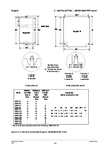
Страница 13: ... washers and nuts MICROMASTER Vector inverters must be secured to a suitable vertical surface by bolts washers and nuts Frame size A units need two bolts or can be DIN rail mounted Frame size B and C units require four bolts Frame size A units need two bolts or can be DIN rail mounted Frame size B and C units require four bolts Figure 2 1 1 Figure 2 1 1 MICROMASTER Vector MICROMASTER Vector Frame ...

Страница 14: ...Model MMVxxx MMVxxx 1 AC 230V 1 AC 230V Class A Class A Filter Filter MMVxxx 2 MMVxxx 2 1 3 AC 1 3 AC 230V 230V Without Without Filter Filter MMVxxx 3 MMVxxx 3 3 AC 380 3 AC 380 500V 500V Without Without Filter Filter Frame Sizes Frame Sizes all measurements in mm all measurements in mm MMV12 MMV12 MMV25 MMV25 MMV37 MMV37 MMV55 MMV55 MMV75 MMV75 MMV110 MMV110 MMV150 MMV150 MMV220 MMV220 MMV300 MMV...

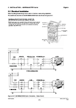
Страница 15: ... L3 3 L2 L2 L1 L1 P PE E P PE E P PE E V V V V U U U U MOTOR MOTOR FUSES FUSES CONTACTOR CONTACTOR FILTER FILTER L L3 3 MICROMASTERVector MICROMASTERVector L L1 1 L L2 2 L3 L3 L L2 2 L L1 1 P PE E P PE E P PE E V V V V U U U U MOTOR MOTOR THREEPHASE THREEPHASE TYPICAL INSTALLATION TYPICAL INSTALLATION SINGLE PHASE SINGLE PHASE Figure 2 2 1 Figure 2 2 1 MICROMASTER Vector Connectors MICROMASTER Vec...

Страница 16: ...ng beneath the inverter inverter Frame size C Frame size C use a small bladed screwdriver use a small bladed screwdriver as shown in Figure 2 2 3 as shown in Figure 2 2 3 to release the gland plate and the to release the gland plate and the fan housing allow them both to swing down to hang beneath the inverter fan housing allow them both to swing down to hang beneath the inverter Connect the cable...

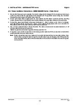
Страница 17: ... and earth PE as shown in Figure 2 2 1 using a 3 core cable for single phase units or a 4 core cable for and earth PE as shown in Figure 2 2 1 using a 3 core cable for single phase units or a 4 core cable for three phase units For the cross section of each core see section 8 three phase units For the cross section of each core see section 8 4 4 Use a 4 core screened Use a 4 core screened cable to ...

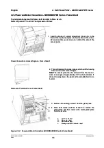
Страница 18: ...nd E to release the gland plate and then remove the metal gland plate gland plate and then remove the metal gland plate from the inverter from the inverter 1 1 Insert the blade of a small sc Insert the blade of a small screwdriver into slot A in the rewdriver into slot A in the front of the inverter and press in the direction of the arrow front of the inverter and press in the direction of the arr...

Страница 19: ...ully measure and cut the cable cut the cable leads for the leads for the control connections control connections if required Feed the if required Feed the control cable control cable through the correct gland see Figure 2 2 2 and secure the gland to the metal gland plate through the correct gland see Figure 2 2 2 and secure the gland to the metal gland plate 10 10 Carefully feed the power and cont...

Страница 20: ...and p d pla late te re rele leas ase t e tab abs s D D C Co on nt tr ro ol l c ca ab bl le e i in np pu ut t E E M Ma ai in ns s c ca ab bl le e i in np pu ut t F F M Mo ot to or r c ca ab bl le e o ou ut tp pu ut t G G B Br ra ak ki in ng r g re es si is st to or r D DC C l li in nk c k ca ab bl le i e in np pu ut t H H J J H H F Fa an n c co on nn ne ec ct to or r J J F Fa an n H Ho ou us si in ...

Страница 21: ...for three phase units For able for three phase units For the cross section of each core see section 8 the cross section of each core see section 8 5 5 Use a 4 core Use a 4 core screened cable to screened cable to connect the motor connect the motor 6 6 Carefully measure and cut the cable Carefully measure and cut the cable leads for power connections motor connections leads for power connections m...

Страница 22: ... RL1A RL1A NC NC RL1B RL1B NO NO RL1C RL1C COM COM RL2B RL2B NO NO RL2C RL2C COM COM P P P PE E P5V P5V N N 2 23 3 2 24 4 2 25 5 2 26 6 RS485 RS485 for USS protocol for USS protocol Note Note ForPTCmotorthermal ForPTCmotorthermal protection P087 1 protection P087 1 Front Panel Front Panel RS485 D type RS485 D type N N 0 0V V 5V max 250mA 5V max 250mA P P PE case PE case 6 6 1 1 5 5 9 9 Figure 2 2 ...

Страница 23: ...ed motors require de rating for continuous operation at low frequencies To ensure that motors are protected against overheating under these conditions it is strongly recommended that a PTC temperature sensor is fitted against overheating under these conditions it is strongly recommended that a PTC temperature sensor is fitted to the motor and connected to the inverter control terminals as shown in...

Страница 24: ...3 L L1 N L2 L3 4 4 B B 15 15 26 26 25 25 24 24 23 23 22 22 21 21 20 20 13 13 14 14 5 5 PE PE B DC B DC 1 1 10V 10V 0 0V V O OR R P PE E 16 16 0 10V 0 10V 2 10V 2 10V 0 20mA 0 20mA 4 20mA 4 20mA I I AIN1 AIN1 AIN1 AIN1 PE PE 4 7 k 4 7 kΩ Ω AOUT AOUT AIN2 PID AIN2 PID R RL L2 2 P P N N RS485 RS485 A AD D AIN2 PID AIN2 PID 6 6 7 7 8 8 9 9 12 12 24 24V V 10 10 11 11 O OR R 15V 15V DIN1 DIN1 DIN2 DIN2 ...

Страница 25: ...E as well as the relevant regulations regarding the correct on high voltage installations e g VDE as well as the relevant regulations regarding the correct use of tools and personal protective gear use of tools and personal protective gear Mount the inverter vertically to a flat non combustible surface Make sure that the unobstructed Mount the inverter vertically to a flat non combustible surface ...

Страница 26: ...th D H1 H1 Depth D Depth D H H H H H1 H1 8 5 mm 8 5 mm Frame Sizes 4 5 and 6 Frame Sizes 4 5 and 6 4 bolts M8 4 bolts M8 4 nuts M8 4 nuts M8 4 washers M8 4 washers M8 W1 W1 W1 W1 W W W W 8 5 mm 8 5 mm 6 bolts M8 6 bolts M8 6 nuts M8 6 nuts M8 6 washers M8 6 washers M8 Frame Size 7 Frame Size 7 Figure 3 1 2 Figure 3 1 2 Mechanical Installa Mechanical Installation Diagram M tion Diagram MIDIMASTER V...

Страница 27: ...0 0 x x 2 21 10 0 2 23 35 5 5 53 30 0 6 6 2 27 75 5 x x 6 65 50 0 x x 2 28 85 5 2 23 35 5 6 63 30 0 7 7 4 42 20 0 x x 8 85 50 0 x x 3 31 10 0 3 37 74 4 8 83 30 0 IP20 NEMA 1 with integrated EMC IP20 NEMA 1 with integrated EMC class A filter class A filter W W H H D D W W1 1 H H1 1 4 4 27 275 5 x 7 x 700 00 x x 21 210 0 23 235 5 68 680 0 5 5 2 27 75 5 x x 8 80 00 0 x x 2 21 10 0 2 23 35 5 7 78 80 0...

Страница 28: ...tors on the MIDIMASTER Vector are shown in Figure 3 2 1 DC DC DC DC D DC C D DC C W W L L1 1 L L2 2 L L3 3 P PE E P PE E 20 20 19 19 18 18 17 17 16 16 15 15 14 14 13 13 12 12 11 11 10 10 9 9 8 8 7 7 6 6 5 5 4 4 3 3 2 2 1 1 L L1 1 L L2 2 W W V V U U L3 L3 V V U U 27 27 26 26 25 25 24 24 23 23 22 22 2 2 3 3 1 1 4 4 6 6 5 5 21 21 FS4 5 units FS4 5 units FS6 units FS6 units FS7 units FS7 units PE PE V...

Страница 29: ...nected correctly and the equipment is properly earthed sections 3 2 1 and 3 2 2 Ensure that the leads are connected correctly and the equipment is properly earthed Frame size 4 and 5 Frame size 4 and 5 Tighten up each of the power and motor terminal screws to 1 1 Nm Tighten up each of the power and motor terminal screws to 1 1 Nm Frame size 6 Frame size 6 Tighten up each of the power and motor ter...

Страница 30: ... 1 3 14 4 1 15 5 1 19 9 1 16 6 1 17 7 1 18 8 2 20 0 A A1 1O OU UT T A AO OU UT T P PT TC C P PT TC C D DI IN N5 5 D DI IN N6 6 Digital Inputs Digital Inputs 7 5 33V max 5mA 7 5 33V max 5mA Motortemp protectioninput Motortemp protectioninput RL1A RL1A NC NC RL1B RL1B NO NO RL1C RL1C COM COM 2 21 1 2 22 2 RL2B RL2B NO NO RL2C RL2C COM COM N N A A2 2O OU UT T P PE E P5V P5V P P 2 23 3 2 24 4 2 25 5 2...

Отзывы: