


1
1.
.
O
OV
VE
ER
RV
VIIE
EW
W
E
En
ng
glliis
sh
h
© Siemens plc 1999
© Siemens plc 1999
G85139-H1751-U529-D1
G85139-H1751-U529-D1
77
4/8/99
4/8/99
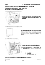
1.1 Installation - General notes
1.1 Installation - General notes
Environmental Requirements
Environmental Requirements
H
Ha
az
za
arrd
d
N
No
otte
es
s
Ideal Installation
Ideal Installation
Temperature
Temperature
Altitude
Altitude
Shock
Shock
Vibration
Vibration
Electro-
Electro-
Magnetic
Magnetic
Radiation
Radiation
Atmospheric
Atmospheric
Pollution
Pollution
Water
Water
Overheating
Overheating
Min. Operating = 0
Min. Operating = 0
°°
C
C
Max. Operating = 50
Max. Operating = 50
°°
C (MMV)
C (MMV)
Max. Operating = 40
Max. Operating = 40
°°
C (MDV)
C (MDV)
If the Inverter is to be installed at an altitude >1000m,
If the Inverter is to be installed at an altitude >1000m,
derating will be required.(Refer to DA64 Catalogue)
derating will be required.(Refer to DA64 Catalogue)
Do not drop the inverter or expose to sudden shock.
Do not drop the inverter or expose to sudden shock.
Do not install the inverter in an
Do not install the inverter in an area where it is likely to
area where it is likely to
be exposed to constant vibration.
be exposed to constant vibration.
Do not install the inverter near sources of electro-
Do not install the inverter near sources of electro-
magnetic radiation.
magnetic radiation.
Do not install the inverter in an environment, which
Do not install the inverter in an environment, which
contains atmospheric pollutants such as dust,
contains atmospheric pollutants such as dust,
corrosive gases, etc.
corrosive gases, etc.
Take care to site the inverter away from potential
Take care to site the inverter away from potential
water hazards. e.g. Do not install the
water hazards. e.g. Do not install the inverter beneath
inverter beneath
pipes that are subject to
pipes that are subject to condensation. Avoid installing
condensation. Avoid installing
the inverter where excessive humidity and
the inverter where excessive humidity and
condensation may occur.
condensation may occur.
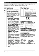
Ensure that the inverter’s air vents are not obstructed,
Ensure that the inverter’s air vents are not obstructed,
including the air vent at the front of the unit, which
including the air vent at the front of the unit, which
should be
should be at least 15mm
at least 15mm from any obstruction.
from any obstruction.
Additional ventilation
Additional ventilation may be required for horizontal
may be required for horizontal
mounting.
mounting.
Make sure that there is an adequate air-flow through
Make sure that there is an adequate air-flow through
the cabinet, as follows:
the cabinet, as follows:
1.
1. Using
Using the
the formula
formula below,
below, calculate
calculate the
the air-flow
air-flow
required:
required:
Air-flow (m3 / hr) = (Dissipated Watts /
Air-flow (m3 / hr) = (Dissipated Watts /
∆
∆
T) x 3.1
T) x 3.1
2.
2. If
If necessary,
necessary, install
install cabinet
cabinet cooling
cooling fan(s).
fan(s).
Note
Note
::
Dissipation (Watts) = 3-5% of inverter rating.
Dissipation (Watts) = 3-5% of inverter rating.
∆
∆
T = Allowable temperature rise within cabinet in °C.
T = Allowable temperature rise within cabinet in °C.
3.1 = Specific heat of air at sea level.
3.1 = Specific heat of air at sea level.
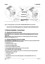
160 mm
160 mm
100 mm
100 mm
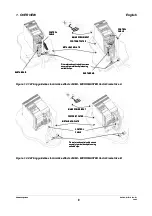
Figure: 1.1
Figure: 1.1
Note: The Plastic Material of the case can be degraded by oil or grease. Care should be taken to
Note: The Plastic Material of the case can be degraded by oil or grease. Care should be taken to
ensure that
ensure that the mounting surface and fixings
the mounting surface and fixings are thoroughly degreased before use.
are thoroughly degreased before use.