


E
En
ng
glliis
sh
h
3
3.
. IIN
NS
ST
TA
AL
LL
LA
AT
TIIO
ON
N
–
–
M
MIID
DIIM
MA
AS
ST
TE
ER
R
V
Ve
ec
ctto
or
r
G85139-H1751-U529-D1
G85139-H1751-U529-D1
© Siemens plc 1999
© Siemens plc 1999
4/8/99
4/8/99
28
28
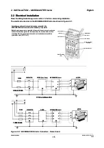
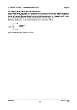
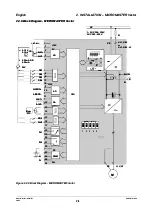
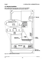
3.2
3.2 Electrical
Electrical Installation
Installation
Read the Wiring Guidelines given in section 1.2 before commencing installation.
Read the Wiring Guidelines given in section 1.2 before commencing installation.
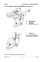
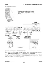
The electrical connectors on the MIDIMASTER Vector are shown in Figure 3.2.1.
The electrical connectors on the MIDIMASTER Vector are shown in Figure 3.2.1.
DC+
DC+
DC-
DC-
D
DC
C--D
DC
C+
+
W
W
L
L1
1 L
L2
2 L
L3
3
P
PE
E P
PE
E
20
20
19
19
18
18
17
17
16
16
15
15
14
14
13
13
12
12
11
11
10
10
9
9
8
8
7
7
6
6
5
5
4
4
3
3
2
2
1
1
L
L1
1
L
L2
2
W
W
V
V
U
U
L3
L3
V
V
U
U
27
27
26
26
25
25
24
24
23
23
22
22
2
2 3
3
1
1
4
4 6
6
5
5
21
21
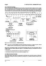
FS4/5 units
FS4/5 units
FS6 units
FS6 units
FS7 units
FS7 units
PE
PE
V
V
U
U
L1
L1
L2
L2
L3
L3
DC-
DC-
W
W
DC+
DC+
PE
PE
FS6 units
FS6 units
Power and
Power and
Motor terminals
Motor terminals
Control
Control
terminals
terminals
DIP switches
DIP switches
Note:
Note:
Switch 6 not used
Switch 6 not used
Jog
Jog
P
P
Figure 3.2.1:
Figure 3.2.1: MIDIMASTER Vect
MIDIMASTER Vector Connectors
or Connectors