


E
En
ng
glliis
sh
h
2
2.
. IIN
NS
ST
TA
AL
LL
LA
AT
TIIO
ON
N –
– M
MIIC
CR
RO
OM
MA
AS
ST
TE
ER
R V
Ve
ec
ctto
or
r
G85139-H1751-U529-D1
G85139-H1751-U529-D1
© Siemens plc 1999
© Siemens plc 1999
4/8/99
4/8/99
22
22
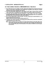
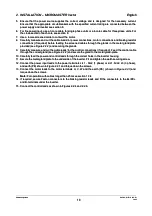
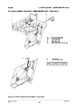
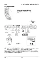
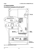
2.2.4
2.2.4 Control
Control Connections
Connections
Output Relays
Output Relays
max. 2.0A / 110 V AC
max. 2.0A / 110 V AC
0.8 A / 230 V AC
0.8 A / 230 V AC
(overvoltage cat.2)
(overvoltage cat.2)
or
or
2A / 30 V DC
2A / 30 V DC
resistive ratin
resistive ratin
Control Terminals
Control Terminals
1
12
1
2
13
1
3
14
1
4
15
5
1
19
9
1
16
6
1
17
7
1
18
8
2
20
0
2
21
1
2
22
2
A
AO
OU
UT
T+
+ A
AO
OU
UT
T--
P
PT
TC
C
P
PT
TC
C
D
DIIN
N5
5 D
DIIN
N6
6
Digital Inputs
Digital Inputs
(7.5 - 33 V, max.5 mA)
(7.5 - 33 V, max.5 mA)
1
1
2
2
3
3
4
4
8
8
5
5
6
6
7
7
9
1
9
10
0
1
11
1
Power Supply for
Power Supply for
PID Feedback
PID Feedback
Transducer
Transducer
(+15 V, max. 50 mA)
(+15 V, max. 50 mA)
Power Supply
Power Supply
(+10 V, max. 10 mA)
(+10 V, max. 10 mA)
An
Anal
alog
ogue
ue In
Inpu
put
t 1
1
-10 V to +10 V
-10 V to +10 V
0/2
0/2
⇒
⇒
1
10
0 V
V
(input impedance 70 k
(input impedance 70 k
Ω
Ω
))
o
or r
0/4
0/4
⇒
⇒
20 mA
20 mA
(resistance = 300
(resistance = 300
Ω
Ω
))
Digital Inputs
Digital Inputs
(7.5 - 33 V, max. 5 mA)
(7.5 - 33 V, max. 5 mA)
P
P1
10
0+
+
0
0V
V
A
AIIN
N+
+
A
AIIN
N--
P15+
P15+
D
DIIN
N1
1 D
DIIN
N2
2 DIN3
DIN3
PIDIN-
PIDIN-
DIN4
DIN4
PIDIN+
PIDIN+
An
Anal
alog
ogue
ue iinp
nput
ut 2
2
0
0
⇒
⇒
10
10 V
V
or
or
0
0
⇒
⇒
20 mA
20 mA
A
Ana
nalo
logu
gue
e O
Out
utp
put
ut
0/4 - 20 mA
0/4 - 20 mA
(500
(500
Ω
Ω
load)
load)
Motor temp. protection input
Motor temp. protection input
RL1A
RL1A
(NC)
(NC)
RL1B
RL1B
(NO)
(NO)
RL1C
RL1C
(COM)
(COM)
RL2B
RL2B
(NO)
(NO)
RL2C
RL2C
(COM)
(COM)
P
P+
+
P
PE
E
P5V+
P5V+
N
N--
2
23
3
2
24
4
2
25
5
2
26
6
RS485
RS485
(for USS protocol)
(for USS protocol)
Note:
Note:
For PTC motor thermal
For PTC motor thermal
protection, P087 = 1
protection, P087 = 1
Front Panel
Front Panel
RS485 D-type
RS485 D-type
N
N--
0
0V
V
5V (max. 250mA)
5V (max. 250mA)
P
P+
+
PE (case)
PE (case)
6
6
1
1
5
5
9
9
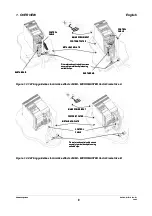
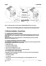
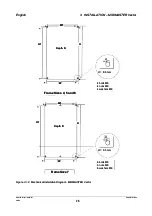
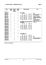
Figure 2.2.4:
Figure 2.2.4: Control Connections
Control Connections - MICROMASTER
- MICROMASTER Vector
Vector
Note:
Note:
Do not use the internal RS485 connections (terminals 24 and 25) if you intend using the external
Do not use the internal RS485 connections (terminals 24 and 25) if you intend using the external
RS485 connection on the front panel e.g. to connect a Clear Text Display (OPM2).
RS485 connection on the front panel e.g. to connect a Clear Text Display (OPM2).
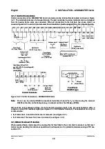
DIP switches
DIP switches select between
select between voltage (V)
voltage (V) and current
and current ((
II
))
analogue inputs and also select either a voltage or
analogue inputs and also select either a voltage or
current feedback signal
current feedback signal
(see Figure 4.1.2: DIP Selector Switches).
(see Figure 4.1.2: DIP Selector Switches).
These switches can only be accessed when
These switches can only be accessed when
the flap in
the flap in the the front
the the front cover is
cover is raised
raised
(see Figure 2.2.1).
(see Figure 2.2.1).
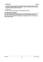
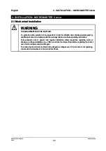
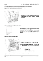
Insert small blade screwdriver (max. 3.5 mm)
Insert small blade screwdriver (max. 3.5 mm)
as shown, while inserting control wire from
as shown, while inserting control wire from
below. Withdraw the screwdriver to secure
below. Withdraw the screwdriver to secure
the wire.
the wire.