


E
En
ng
glliis
sh
h
3
3.
. IIN
NS
ST
TA
AL
LL
LA
AT
TIIO
ON
N
–
–
M
MIID
DIIM
MA
AS
ST
TE
ER
R
V
Ve
ec
ctto
or
r
G85139-H1751-U529-D1
G85139-H1751-U529-D1
© Siemens plc 1999
© Siemens plc 1999
4/8/99
4/8/99
30
30
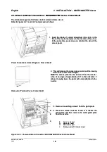
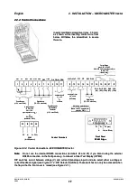
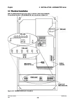
3.2.2
3.2.2 Control
Control Connections
Connections
Control connections to the MIDIMASTER Vector are made via two terminal blocks located as shown in Figure
Control connections to the MIDIMASTER Vector are made via two terminal blocks located as shown in Figure
3.2.1. The terminal blocks are of a two-part design. The part containing the screw terminals can be unplugged
3.2.1. The terminal blocks are of a two-part design. The part containing the screw terminals can be unplugged
from it’s housing before wires are connected. When all connections to the terminals have been made (
from it’s housing before wires are connected. When all connections to the terminals have been made (
as
as
shown in Figures 3.2.1 and 3.2.2
shown in Figures 3.2.1 and 3.2.2
) and secured, the terminal block must be plugged firmly back into it’s housing.
) and secured, the terminal block must be plugged firmly back into it’s housing.
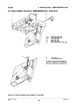
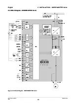
1
1
2
2
3
3
4
4
8
8
5
5
6
6
7
7
9
1
9
10
0
1
11
1
Power Supply
Power Supply
for PID Feedback
for PID Feedback
Transducer
Transducer
(+15 V, max. 50 mA)
(+15 V, max. 50 mA)
Power Supply
Power Supply
(+10 V, max. 10 mA)
(+10 V, max. 10 mA)
An
Ana
alo
logu
gue
e In
Inpu
put
t 1
1
-10 V to +10 V
-10 V to +10 V
0/2
0/2
⇒
⇒
1
10
0 V
V
(input impedance 70 k
(input impedance 70 k
Ω
Ω
)
)
o
or
r
0/4
0/4
⇒
⇒
20 mA )
20 mA )
(Resistance = 300
(Resistance = 300
Ω
Ω
)
)
Output Relays (RL1 and RL2)
Output Relays (RL1 and RL2)
max. 0.8 A / 230 V AC
max. 0.8 A / 230 V AC
(overvoltage cat.2)
(overvoltage cat.2)
2.0 A / 30 V DC
2.0 A / 30 V DC
(resistive rating)
(resistive rating)
Digital Inputs
Digital Inputs
(7.5 - 33 V, max. 5 mA)
(7.5 - 33 V, max. 5 mA)
P
P1
10
0+
+
0
0V
V
A
AIIN
N+
+
A
AIIN
N--
P15+
P15+
D
DIIN
N1
1 D
DIIN
N2
2
D
DIIN
N3
3
PIDIN-
PIDIN-
Control Terminals
Control Terminals
D
DIIN
N4
4
P
PIID
DIIN
N+
+
A
Ana
nalo
logu
gue
e in
inpu
put
t 2
2
0
0
⇒
⇒
10
10 V
V
o
or
r
0
0
⇒
⇒
20 mA
20 mA
An
Anal
alog
ogu
ue
e O
Ou
utp
tpu
ut
t 2
2
0/4 - 20 mA
0/4 - 20 mA
(500
(500
Ω
Ω
load)
load)
use with terminal 13
use with terminal 13
A
Ana
nallog
ogue
ue O
Out
utp
put
ut 1
1
0/4 - 20 mA
0/4 - 20 mA
(500
(500
Ω
Ω
load)
load)
1
12
1
2
13
1
3
14
4
1
15
5
1
19
9
1
16
6
1
17
7
1
18
8
2
20
0
A
A1
1O
OU
UT
T+
+ A
AO
OU
UT
T-- P
PT
TC
C
P
PT
TC
C D
DIIN
N5
5 D
DIIN
N6
6
Digital Inputs
Digital Inputs
(7.5 - 33 V, max. 5 mA)
(7.5 - 33 V, max. 5 mA)
Motor temp.protection input
Motor temp.protection input
RL1A
RL1A
(NC)
(NC)
RL1B
RL1B
(NO)
(NO)
RL1C
RL1C
(COM)
(COM)
2
21
1
2
22
2
RL2B
RL2B
(NO)
(NO)
RL2C
RL2C
(COM)
(COM)
N
N--
A
A2
2O
OU
UT
T+
+
P
PE
E
P5V+
P5V+
P
P+
+
2
23
3
2
24
4
2
25
5
2
26
6 2
27
7
RS485
RS485
(for USS protocol)
(for USS protocol)
Note:
Note:
For
For PTC motor th
PTC motor thermal
ermal
protection,
protection, P087
P087 =
= 1
1
Front Panel
Front Panel
RS485 D-type
RS485 D-type
N
N--
0
0V
V
5V(max.250mA)
5V(max.250mA)
P
P+
+
PE (case)
PE (case)
6
6
1
1
5
5
9
9
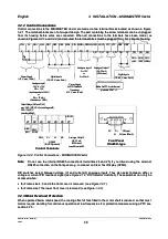
Figure
Figure 3.2.2:
3.2.2: Control
Control Connections
Connections -
- MIDIMASTER
MIDIMASTER Vector
Vector
Note:
Note:
Do not use the internal RS485 connections (terminals 24 and 25) if you intend using the external
Do not use the internal RS485 connections (terminals 24 and 25) if you intend using the external
RS485 connection on the front panel e.g. to connect an Clear Text Display (OPM2).
RS485 connection on the front panel e.g. to connect an Clear Text Display (OPM2).
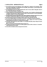
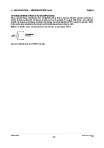
DIP switches
DIP switches select between
select between voltage (V)
voltage (V) and current
and current ((
II
) analogue inputs. They also select between either a
) analogue inputs. They also select between either a
voltage or current PID feedback signal (
voltage or current PID feedback signal (
see Figure 4.1.2: DIP Selector Switches
see Figure 4.1.2: DIP Selector Switches
). These switches can only be
). These switches can only be
accessed when:
accessed when:
••
for
for Frame si
Frame size
ze 4,
4, 5
5 and
and 6
6 the
the front
front cover
cover is
is removed
removed
(see Figure 3.2.1).
(see Figure 3.2.1).
••
for Frame
for Frame size 7
size 7 the lower
the lower front cover
front cover is removed
is removed ((
see Figure 3.2.1
see Figure 3.2.1
).
).
3.2.3 Motor Overload Protection
3.2.3 Motor Overload Protection
When operated below rated speed, the cooling effect of fans fitted to the motor shaft is reduced. so that most
When operated below rated speed, the cooling effect of fans fitted to the motor shaft is reduced. so that most
motors require de-rating for continuous operation at low frequencies. For protection measures using a PTC see
motors require de-rating for continuous operation at low frequencies. For protection measures using a PTC see
section 2.2.5.
section 2.2.5.