- 20 -
0-0 Basic screen
2-0
ENT
DISP
DISP
2-1
to the 2--2 screen
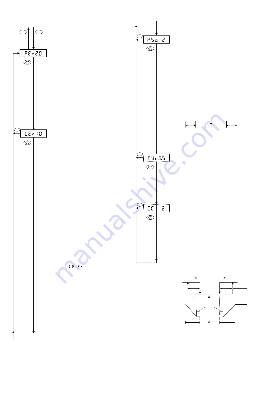
(1) Setting Delay Time upon Occurrence of
Position Error
Screen for setting delay time upon
occurrence of position error
Initial value: 2.0 seconds
Setting range: 0.0~9.9 seconds
A delay time from the detection of
position error to the position error is set.
If a position error occurs while the 0-0
basic screen is on display, the 0-0-2
position display screen returns and the
2 digits on the right blink to signify a
position error.
If a position error occurs while any
screen other than the 0-0 basic screen is
on display, the POSITION lamp blinks.
(2) Setting Detection Time for Control Loop
Error
Control loop error detection time setting
screen
Initial value: 10 seconds
Setting range: 5~60 seconds
A control loop error means that a
feedback potentiometer input signal does
not correspond to control output. The
response of the feedback potentiometer
to control output changes in accordance
with the speed of a control motor to be
used. In case the speed of motor is high
(the time between full close and full open
is short) and it is intended to quicken the
control loop error detection, a shorter
detection time is set. In this case, lower
motor speed tends to result in erroneous
detection. An excessively low motor
speed (the time between full close and
full open is longer than 250 seconds)
makes a change per unit time of the
feedback potentiometer very small,
leading to the possibility that a normal
condition is taken as a control loop error.
If this is the case, set a longer time for
control loop error detection.
Use 4% or more of the time between full
close and full open as a guideline for
your setting.
When a control loop error occurs on the
DES/DEV display screen, the error
message appears. At the same
time, the 2 digits from the right blink and
the DES/DEV lamp lights.
In case a control loop error and a position
error occur simultaneously, the position
error is given preference and the control
loop error check is released.
Refer to the following formula in setting
the control loop error detection time.
Set value of control loop error detection
time > 4 x T/G
T : Motor action time (second)
G: Motor speed adjustment setting (%)
Even when a position error is not
detected in the case of R1 or R3 break,it
may be detected as a control loop error.
5 seconds
2-2
2-3
(3) Setting of Position Error Range
Position error range setting screen
Initial value: 2%
Setting range: 1 ~10%
What percentage by which a position
value is deviated from the 1 to 100%
range is to be judged as a position error
(position scaleover) is set.
In case the position error range is set at
3%, a value lower than
-
3% or more than
103% is judged as a position error.
In setting a position error range, a value
to be set should be within a residual
resistance range from the limiter switch
to the potentiometer. A value set outside
the residual resistance range is not taken
as a position error but a control loop
error is output.
(4)
Setting of Cycle Time of Motor Speed
Adjustment
Motor speed adjustment cycle time
setting screen
Initial value: 0.5 seconds
Setting range: 0.5~9.9 seconds
In the case of SSR output, a cycle time of
motor speed adjustment is set. For setting
motor speed adjustment, see 1-32 Motor
adjustment setting screen.
(5)
Setting of Inching Action Range
Inching action range setting screen
Initial value: OF
Setting range: OF, 1~10%
(OF: No inching action)
When the absolute value of deviation enters
the inching action range, the deviation value
and the proportional inching action will
automatically take place.
(However, setting is possible only in case of
SSR output)
Potentiometer
Limit switch
0%
R1
R2
R3
100%
Limit switch
Residual
resistance
Residual
resistance
DISP
2-4
DISP
DISP
Example: Relations of inching action, dead
band and hysteresis.
(When motor speed G=100%)
continued to the right top
Output
ON
Output
OFF
Dead band DB
Target value
of position
Hysteresis
0.5%
100%
10%
Motor speed G
Inching action
setting range
Inching action
setting range


