BEAM DETECTOR MAINTENANCE AND CONTROL
N
ormal conditions of installation require maintenance intervals as indicated by current regulations of the proper country.
These intervals, on the basis of every 6 months, may sometimes be more frequent depending on the many kinds of
conditions of application of the devices, especially in industrial environments where there may be stationary dust and
steam or the products of various production stages.
MAINTENANCE
The maintenance of the ILIA line does not require particular equipment and is both simple and fast.
The operation is carried according to the following procedure:
1.
Clean the detector with water and/or neutral soap without the use of abrasive cloths and solvents. With a soft
cloth clean the outer surface of the frontal parts of the all units. If the surfaces are very scratched, yellowed or
significantly dimmed, they must be replaced by qualified personnel as this may jeopardise the proper optical
working of the detector.
2.
It is mandatory to substitute the detectors that have mechanical or optical damages with new detectors.
3.
Check the correct infrared signal level trough the menu < adjustment >, observing conformity of the Led signals.
It is advisable in any case to adjust the level of Rx at 100%
(sere note at pag. 72)
. If the value of the Rx is too low,
repeat the alignment procedure until saturation point, and repeat the <Autoadjust> procedure.
4.
Check the Alarm conditions, the Fault conditions and the corresponding outputs, following “Alarm Test” and
“Fault Test” procedures as set forth in the chapter “CALIBRATION AND ASSEMBLY PROCEDURE” at page 54
or 63.
NOTE
The controller does not require specific maintenance. During maintenance on detectors check on correct
keyboard workding and that the menu messages correspond to correct repeating led functions.
ADDITIONAL CONTROLS
SIGNAL DROP
If the infrared signal carried emitted by the detector tends over times to fall in intensity, the system will carry out a
proportional up rating by way of long term self-regulated compensation). If the infrared signal falls to the minimum set
threshold due to the build up of dust or settling of the building structure to which the equipment is fastened, an green Led
will flash locally as a warning. The consequent opening of the fault contact will send the detector control unit a
maintenance request.
INSUFFICIENT SIGNAL / FAULT
When the infrared signal emitted by the detector falls below a minimum level or is interrupted by an obstacle, the “fault”
contact will open, rather than that of “fire alarm”.
When the correct signal level has returned or the obstacle removed the detector will return to normal working in less than
one second. The detection units currently have memory retention also of fault conditions so if the detector comes
immediately back into service, on removal of the obstacle it must always be checked that the control unit locally resets the
fault signal, whether it be visual or sound.
ALARM
A red Led will indicated the start of a fire detection without enabling an output. After a certain analysis time, typically 16
seconds, the red Led will start flashing and the output will be enabled to signal alarm confirmation or by the MRS module,
if connected (see pag. 82).
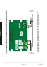
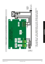
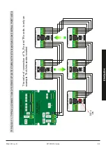
TEST FOR RING-CONFIGURATION BY YEARLY MAINTENANCE
Before the test: take sure that the system is running and the controller display shows <<Normal Operation>>
1.
Disconnect the two terminals "power output" and "serial line" of the main module.
2.
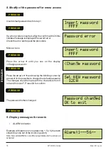
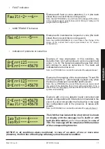
Wait 5 seconds and check that the display shows: "A-Err: 123 ..." (until the last programmed detectors) and "B-Err: --------
3.
Reconnect the terminals and perform the same operation with the two terminals "power output" and "serial line B" of
the expansion module.
4.
Wait 5 seconds and check that the display shows: "A-Err: --------" and "A-Err: 123 ..." (until the last of the detectors
programmed).
5.
If the display shows "C-Err: 123 ..." (until the last of the detectors programmed) and "Fault: 123 ..." (until the last of the
detectors programmed) even after waiting for 5 seconds, then there is a break in the supply line.
6.
Reconnect the cables and make sure that the clamps are inserted securely.
ENGLISH
86
Mod. MII
rev. 01
SETRONIC Verona
Содержание ILIA ERHSO712
Страница 1: ......
Страница 3: ...ENGLISH MANUAL ...
Страница 4: ......
Страница 6: ...HIGH SENSITIVITY LINEAR BEAM DETECTOR MODEL ERHS0712 ENGLISH 50 Mod MII rev 01 SETRONIC Verona ...
Страница 15: ...HIGH SENSITIVITY REFLECTION SYSTEM DETECTOR MODEL ERRHS0712 ENGLISH Mod MII rev 01 SETRONIC Verona 59 ...
Страница 24: ...CONTROLLER FOR BEAM DETECTOR MODEL CSRLS MODEL CSRLS Dust 68 Mod MII rev 01 SETRONIC Verona ENGLISH ...


