background image

ENGLISH

66

Mod. MII 

rev. 01

SETRONIC Verona

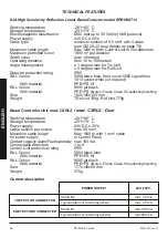
TECHNICAL FEATURES

ILIA High Sensitivity Reflection Linear Beam Detector model ERRHS0712

Working temperature 

-20°/+65° C

Storage temperature 

-20°/+70° C

Electromagnetic disturbance 

EMC test up to 30 Volt/m (VdS protocol)

Power supply 

2


4V DC ± 20%

Cable type 

minimum section of 0,5 mm² with 4 wires


type CEI 20-22 (see details on page 78)

Maximum cable length 

max 1200 m from Control Unit to line detectors 

Maximum permitted cover 

1600 m² per detector  

Width cover 

max 15 meters 

Operating distance 

from 10 to 150 meters

Angle misalignment 

± 1 degree max for Trx Unit


± 5 degree max for Ref Unit 

Detector protection rating 

IP65

RAL Colour 

5004 black blue, front cover 5005 signal blue


1013 oyster white

 (on request)


With material 

PPE+PS HI

RAL Colour 

9005 jet black


With material 

PPE+PS 

«Noryl» Flame Class V0 selfextinghuishing

Size 

162x145x193 mm

Weight 

TRx Unit 780g, Ref Unit 770g

Beam Controller Unit mod. CSRLS

 / mod. CSRLS - Dust

Working temperature 

-20°/+65° C

Storage temperature 

-20°/+70° C

Power supply 

2


4V DC ± 20%

Cable section per output 

max 0,5 mm²

Maximum cable length 

Max 1000 m with 1 mm² cable

for power supply 

to Control Panel

Contact capacity Alarm/Fault optorelay  max 150 mA 
Connectable detectors 

1 to 8

Control Unit protection rating 

IP65

RAL Colour 

5004 black blue


With material 

PPE+PS HI

RAL Colour 

9005 jet black


With material 

PPE+PS 

«Noryl» Flame Class V0 selfextinghuishing

Size 

177x145x69 mm

Weight 

375g

Current absorption

POWER SUPPLY

24V ± 20%

max  42 mA

0

max  45 mA

0

max 190 mA

max 200 mA

Stand By

1 DETECTOR CONNECTED

8 DETECTORS CONNECTED

Typical (alarm or fault relay active)

Stand By

Typical (alarm or fault relay actives)

Содержание ILIA ERHSO712

Страница 1: ......

Страница 2: ...Prodotto secondo la norma di rispetto ambientale Manufactured in accordance with the regulations and respect for the environment as in Produktion im Einklang mit allen gültigen Umweltschutzbestimmungen 2002 96 CE 01111 Certificazione russa Russian certificate Russisches Zertifikat II Certificazione VdS VdS certification VdS Zertifizierung n G209195 EN 54 17 Costruito in conformità con la Norma Eur...

Страница 3: ...ENGLISH MANUAL ...

Страница 4: ......

Страница 5: ...p 69 1 Menu access protect by password 69 2 Sensibility Setting 69 3 Modify of Transmitter level and check of the signal level received 70 4 Auto calibration of Transmitter level 71 5 Alarm Auto test 73 6 Alarm Reset 74 7 System Configuration 74 8 Modify of the password for menu access 76 9 Display messages for events 76 Choose the right cable 78 Caution for installation 78 Parameter of simple aut...

Страница 6: ...HIGH SENSITIVITY LINEAR BEAM DETECTOR MODEL ERHS0712 ENGLISH 50 Mod MII rev 01 SETRONIC Verona ...

Страница 7: ...g in base to detector connection Ø Base complete with back up board short circuit isolator to ensure continued work even after a short circuit Ÿ Special Allen Key suitable for mechanical alignment diaphragm regulation unhook of detector base and open close of control unit Product characteristics Ÿ Standard EN 54 12 Ÿ Protection rating IP65 Transmitter Unit Receiver Unit and Controller Unit Ÿ RoHS ...

Страница 8: ...ystem continue proper working even if the cables are cut or in the case of a short circuit by the protection circuit inserted in each single detector There are also programmable relay contacts in the Unit for each individual detector connected These relays can have their polarity reversed with the use of the software and permit the transmission to a single central unit of the individual alarm faul...

Страница 9: ...t A message on the display will indicate the type of event and the detector number NOTE The Dip Switch must always be used during installation to determine the detector address number also if is there only one detector In the loop configuration the Dip Switch 4 must stay in the OFF position The connection of one or more detectors is with leads of a minimum cross section 2 in accordance with curren...

Страница 10: ...d must be less than 100 Ω 4 Reconnect the cables and make sure that the clamps are inserted securely CALIBRATION PROCEDURE 1 Power the system via the controller and set the number of detectors connected and the configuration of connection to serial line The controller also allows the use of the two serials in an independent manner as if they were two separate lines open In this case the addresses ...

Страница 11: ...4 Calibration of detection lines with the barriers already previously installed ž press or ƒ until you get to AUTOAdjust press OK ž press or tochangethenumberofthedetectionlinetobeworkedon pressOK ž wait until theTX value stabilises and press OK ž the value of the RX must be about 100 see note at pag 72 ž press OK to confirm the setting 5 Adjustment of detection line sensitivity ž press or ƒ until...

Страница 12: ...ion lines ž press or ƒ until you get to AlarmTest press OK ž press or to edit the number of the detection lines press OK ž press OK to start the alarm testing ž wait for the barrier alarm ž press OK to reset the barriers for details about menu see pag 73 4 Reset the detection lines alarm ž press or ƒ until you get to ResetAlarm press OK ž press OK to reset the alarm ž It is possible to reset the a...

Страница 13: ...ial PPE PS Noryl Flame Class V0 selfextinghuishing Size 162x145x193 mm Weight Tx Unit 735g Rx Unit 775g Beam Controller Unit mod CSRLS mod CSRLS Dust Working temperature 20 65 C Storage temperature 20 70 C Power supply 24V DC 20 Cable section per output max 0 5 mm Maximum cable length Max 1000 m with 1 mm cable for power supply to Control Panel Contact capacity Alarm Fault optorelay max 150 mA Con...

Страница 14: ...aces or in any case to limit its size Receiver Unit Fix the key Turn clockwise Diaphragm position 0 Distance from 30 m up to 200 m Diaphragm position 1 Distance from 50 m up to 180 m Diaphragm position 2 Distance from 40 m up to 170 m Diaphragm position 3 Distance from 30 m up to 150 m Diaphragm position 4 Distance from 15 m up to 120 m Diaphragm position 5 Distance from 10 m up to 80 m 0 10 20 30...

Страница 15: ...HIGH SENSITIVITY REFLECTION SYSTEM DETECTOR MODEL ERRHS0712 ENGLISH Mod MII rev 01 SETRONIC Verona 59 ...

Страница 16: ...ion Ø Base complete with back up board short circuit isolator to ensure continued work even after a short circuit Ÿ Special Allen Key suitable for mechanical alignment diaphragm regulation unhook of detector base and open close of control unit Product characteristics Ÿ Standard EN 54 12 Ÿ Protection rating IP65 Transmitter Receiver Unit Reflection Unit and Controller Unit Ÿ RoHS Compatibility Ÿ Op...

Страница 17: ...ond typology the system continue proper working even if the cables are cut or in the case of a short circuit by the protection circuit inserted in each single detector There are also programmable relay contacts in the unit for each individual detector connected These relays can have their polarity reversed with the use of the software and permit the transmission to a single central unit of the ind...

Страница 18: ...al piece of equipment A message on the display will indicate the type of event and the detector number Note The Dip Switch must always be used during installation to determine the detector address number also if is there only one detector In the loop configuration the Dip Switch 4 must stay in the OFF position The connection of one or more detectors is with leads of a minimum cross section 2 in ac...

Страница 19: ...than 100 Ω 4 Reconnect the cables and make sure that the clamps are inserted securely CALIBRATION PROCEDURE 1 Power the system via the controller and set the number of detectors connected and the configuration of connection to serial line The controller also allows the use of the two serials in an independent manner as if they were two separate lines open In this case the addresses remain the same...

Страница 20: ...ration of detection lines with the detectors already previously installed ž press or ƒ until you get to AUTO Adjust press OK ž press or to change the number of the detection line to be worked on press OK ž wait until the TX value stabilises and press OK ž the value of the RX must be about 100 see note at pag 72 ž press OK to confirm the setting 5 Adjustment of detection line sensitivity ž press or...

Страница 21: ...irm the setting 3 Alarm simulation for detection lines ž press or ƒ until you get to Alarm Test press OK ž press or to edit the number of the detection lines press OK ž press OK to start the alarm testing ž wait for the barrier alarm ž press OK to reset the barriers for details about menu see pag 73 4 Reset the detection lines alarm ž press or ƒ until you get to Reset Alarm press OK ž press OK to ...

Страница 22: ...on request With material PPE PS HI RAL Colour 9005 jet black With material PPE PS Noryl Flame Class V0 selfextinghuishing Size 162x145x193 mm Weight TRx Unit 780g Ref Unit 770g Beam Controller Unit mod CSRLS mod CSRLS Dust Working temperature 20 65 C Storage temperature 20 70 C Power supply 24V DC 20 Cable section per output max 0 5 mm Maximum cable length Max 1000 m with 1 mm cable for power supp...

Страница 23: ...w spaces or in any case to limit its size Transmitter Receiver Unit Fix the key Turn clockwise Diaphragm position 0 Distance from 20 m up to 150 m Diaphragm position 1 Distance from 40 m up to 125 m Diaphragm position 2 Distance from 30 m up to 90 m Diaphragm position 3 Distance from 20 m up to 80 m Diaphragm position 4 Distance from 15 m up to 65 m Diaphragm position 5 Distance from 10 m up to 50...

Страница 24: ...CONTROLLER FOR BEAM DETECTOR MODEL CSRLS MODEL CSRLS Dust 68 Mod MII rev 01 SETRONIC Verona ENGLISH ...

Страница 25: ...ters from 0 to 9 and fromAto F If a wrong code is inserted after the confirm with OK the mistake message is displayed Check the error and repeat the procedure With the right password the menu is available Press the arrows is setting the detector of which should be changed the sensitivity and read the noise Waiting for the loading of the data PRESS OK PRESS OK PRESS OK PRESS OK Mod MII rev 01 SETRO...

Страница 26: ...MII rev 01 SETRONIC Verona ENGLISH Press the arrows SMOKE sensitivity will be set 1 Note if the threshold of sensibility is near to the limit of the minimum range requested by the norm you will see Warn f e Smoke 284 Warn 2 Note with the Dust version controller the Warn notice appears also for the smoke threshold 1492 indicating the point from which the Dust threshold starts e g Smoke 3200 Warn wa...

Страница 27: ...change has been made may be has been just made a check of the values the message on the display will be Data not changed OK to exit PRESS OK Insert password as for step 1 PRESS OK Mod MII rev 01 SETRONIC Verona 71 ENGLISH Press the arrows select the Detector which will be regulated the IR power transmission Wait for the loading of the data PRESS OK PRESS OK Press one time to visualize on display a...

Страница 28: ...tallation when the environment is dusty or dirty and especially using the controller in DUST version adjust the transmitter level so that the RX value will be at 90 This to avoid that the detector goes in over signal when the air come back to a clean condition When the detector is up to 100 PRESS OK Wait for saving data 72 Mod MII rev 01 SETRONIC Verona ENGLISH Press the arrows select the Detector...

Страница 29: ...to start the test and wait for the alarm signal LEDAlarm lighted PRESS OK In case of use of the controller in DUST version if the smoke sensitivity threshold of the detector that will be put in test is 2600 set it at 1400 for the time necessary for test then set again the chosen threshold Mod MII rev 01 SETRONIC Verona 73 ENGLISH Insert password FFFF sensibility Alarm Test choose line N 1 Loading ...

Страница 30: ...access menu Press the arrow until to visualize on display ResetAlarm PRESS OK Insert password as for step 1 PRESS OK PRESS OK ENGLISH 74 Mod MII rev 01 SETRONIC Verona Ÿ In hand mode by the menu Ÿ With Remote Reset Module MRS If the Controller is equipped with Remote Reset Module MRS close the terminal blocks and by a clean contact for at least 3 seconds Press OK key to reset Alarm Insert password...

Страница 31: ...s possible to set up the serial line as closed loop Close or Open Error if the wish is to have two different stub lines with n detector connected function available only with expansion card inserted Press the arrows will be active ON or not active OFF the check control of the correct serial line communication Note to be used only if it is necessary make a check of the line for some problems during...

Страница 32: ...hows the zone out of the incoming event Note the Led ALARM is on and the output related to the zone s is activated Press the arrows ƒ and moving the blinking cursor by arrows it is possible to change the default password The changes could be made with the characters from 0 to 9 and fromAto F Press OK for confirm ENGLISH 76 Mod MII rev 01 SETRONIC Verona 8 Modify of the password for menu access Ins...

Страница 33: ...d and in any case the system is still working Example with only one detector really connected and system configuration with 8 Detectors or insulated in the event of a short circuit after the first barrier in the open line configuration and in the presence of bases with guards Note LedTROUBLE is on and will be activated the output of zone 1 NOTICE in all conditions above mentioned in case of an ala...

Страница 34: ...ing or at the end of the line Inside the socket of the detector make a bridge with the shield so that it is continuous from beginning to the end of the line Ÿ The RS485 standard is made for the connection of many numbers of devices in multidrop daisy chain So that they are not allowed shunts or connection in T line mode This means that the wire must pass from the first to the second detector and s...

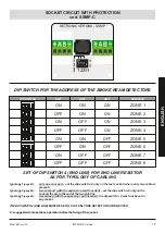
Страница 35: ...85 closed loop with the expansion card inserted the dip switch n 4 must not be set in any socket THE DIPSWITCH 4 END LINE MUST BE SETALSO IF ONLYONE DETECTOR IS CONNECTED It s suggested to make these operation before the fixing of the socket ON ON ON ZONE 1 OFF ON ON ZONE 2 ON OFF ON ZONE 3 OFF OFF ON ZONE 4 ON ON OFF ZONE 5 OFF ON OFF ZONE 6 ON OFF OFF ZONE 7 OFF OFF OFF ZONE 8 ADDRESS SW3 SW2 SW...

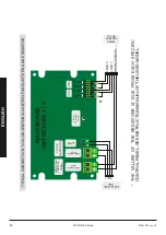
Страница 36: ...PANEL WITH END LINE RESISTOR POWER SUPPLY INPUT POWER SUPPLY OUTPUT SERIAL BUS A FROM THE CONTROL PANEL TO THE DETECTORS DISPLAY CONTRAST ADJUST MAIN BOARD DETECTORS 1 2 A B LINE 2 LINE 1 RESETTABLE POWER SUPPLY TO THE CONTROL PANEL DETECTORS LINE A B OUTPUT DETECTOR 1 OUTPUT DETECTOR 2 ALARM TROUBLE TROUBLE ALARM ENGLISH 80 Mod MII rev 01 SETRONIC Verona ...

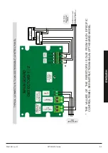
Страница 37: ...EL MAIN BOARD DETECTORS 1 2 A B RESETTABLE POWER SUPPLY TO THE CONTROL PANEL DETECTORS LINE ADDRESS MODULE ADDRESS MODULE ADDRESS LINE A B ALARM TROUBLE TROUBLE ALARM POWER SUPPLY INPUT POWER SUPPLY OUTPUT SERIAL BUS A FROM THE CONTROL PANEL TO THE DETECTORS DISPLAY CONTRAST ADJUST OUTPUT DETECTOR 1 OUTPUT DETECTOR 2 ENGLISH Mod MII rev 01 SETRONIC Verona 81 ...

Страница 38: ...PLAY CONTRAST ADJUST MAIN BOARD DETECTORS 1 2 A B ALARM TROUBLE OUTPUT DETECTOR 1 OUTPUT DETECTOR 2 CLOSE t 2 sec RESET INTERNALLY CONNECTED TO OF THE POWER SUPPLY OPEN NORMAL FUNCTION CLEAN CONTACT RESET INPUT CONNECTION TO MRS RESET MODULE ALARM TROUBLE ENGLISH 82 Mod MII rev 01 SETRONIC Verona ...

Страница 39: ... SSMP SETRONIC VERONA SSMP DIP 4 ON MAIN BOARD DETECTORS 1 2 ALARM TROUBLE TROUBLE ALARM A B TROUBLE ALARM TROUBLE ALARM TROUBLE ALARM TROUBLE ALARM TROUBLE ALARM TROUBLE ALARM OUTPUT DETECTOR 3 OUTPUT DETECTOR 4 OUTPUT DETECTOR 5 OUTPUT DETECTOR 6 OUTPUT DETECTOR 7 OUTPUT DETECTOR 8 TO THE DETECTORS SERIAL BUS B POWER SUPPLY OUTPUT EXPANSION BOARD DETECTORS 3 8 POWER SUPPLY INPUT POWER SUPPLY OUT...

Страница 40: ...XPANSION BOARD DETECTORS 3 8 POWER SUPPLY INPUT POWER SUPPLY OUTPUT SERIAL BUS A FROM THE CONTROL PANEL TO THE DETECTORS DISPLAY CONTRAST ADJUST OUTPUT DETECTOR 1 OUTPUT DETECTOR 2 2 3 4 ON ADDRESS SW END LINE 2 1 3 OFF ON 2 3 4 ON ADDRESS SW END LINE 2 1 3 OFF ON TX RX DETECTOR 1 DETECTOR 2 2 3 4 ON ADDRESS SW END LINE 2 1 3 OFF ON RX DETECTOR 1 2 3 4 ON ADDRESS SW END LINE 2 1 3 OFF ON TX DETECT...

Страница 41: ...EXPANSION BOARD DETECTORS 3 8 POWER SUPPLY INPUT POWER SUPPLY OUTPUT SERIAL BUS A FROM THE CONTROL PANEL TO THE DETECTORS DISPLAY CONTRAST ADJUST OUTPUT DETECTOR 1 OUTPUT DETECTOR 2 2 3 4 ON ADDRESS SW END LINE 2 1 3 OFF ON 2 3 4 ON ADDRESS SW END LINE 2 1 3 OFF ON TX RX DETECTOR 1 DETECTOR 2 2 3 4 ON ADDRESS SW END LINE 2 1 3 OFF ON RX DETECTOR 1 2 3 4 ON ADDRESS SW END LINE 2 1 3 OFF ON TX DETEC...

Страница 42: ...ional up rating by way of long term self regulated compensation If the infrared signal falls to the minimum set threshold due to the build up of dust or settling of the building structure to which the equipment is fastened an green Led will flash locally as a warning The consequent opening of the fault contact will send the detector control unit a maintenance request INSUFFICIENT SIGNAL FAULT When...

Страница 43: ...ted compared with the number configured Ø Check connections on serial line probable inversion of serial cables A and B and check connections from controller to the first and or last base and between one base and another Ø Check that there are not one more end of line switches set on the loop line or more than one the last on an open connection Ø Check the addresses correspondence e g that there ar...

Страница 44: ...cessary If the problem comes back check physical alignment of the two units Ø Indication of Maintenance request are possible also for the presence of steam fog or dust in environment the same could happens with ice on optical frontal part Ø Read the signal received value using the Adjustment menu If the figure is between 104 and 107 lower the Transmitter level to 100 If necessary check the rigidit...

Страница 45: ...sorption of the system Controller Detectors If the value of absorption are the ones shown in technical information it means that no one socket has gone on protection If the protection has been activated or the short circuit is still present the absorption of the line will be superior of around 200 mArespect to the normal operation ones Ø The short circuits on the loop configured line and isolated ...

Страница 46: ... they do not accord with our suggestions We shall consider any such regulations as having been followed as from the date they come into force Keep this booklet close to hand for future reference The information contained in this booklet is available in PDF files at our website www setronicverona com Copyright December 2013 Setronic Verona S r l Setronic is the sole owner of the data and images con...

Страница 47: ...ilable for Ardea and ARGO line too Einstellbarer Montagebügel für die linie ILIA Lieferbar auch für ARDEA und Argo Frontale antipolvere per Overhousing Frontal dust protection for Overhousing Frontal Staubschutz für Schutzgehäuse Custodia di protezione per ambienti speciali Protective Overhousing for Special Environments Schutzgehäuse für spezielle Umgebungen SOHI FAPO SAA G ...

Страница 48: ...Mod MII rev 01 SETRONIC Verona S r l Via F Da Levanto 14 b 37138 VERONA Italy Tel 390458347777 Fax 390458347778 www setronicverona com info setronicverona com ...

Отзывы: