


Installing the LM100 gateway
Senstar LM100 Product Guide
Page 37
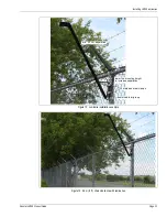
Figure 38: Gateway wiring diagram
Figure 39: Option card wiring diagram
T6 DC power
T5 RS-485
gateway -VDC
INPUT POWER
RS-485
T7 I/O ports 1 - 5
T8 I/O ports 6 - 10
AP B-side data
*
I/O 10 +
I/O 10 -
I/O ports 6 - 10
I/O 9 +
I/O 9 -
I/O 8 +
I/O 8 -
I/O 7 +
I/O 7 -
I/O 6 +
I/O 6 -
I/O 1 -
I/O 1 +
I/O ports 1 - 5
I/O 2 -
I/O 2 +
I/O 3 -
I/O 3 +
I/O 4 -
I/O 4 +
I/O 5 -
I/O 5 +
AP A-side data
*
(12 to 48 VDC)
gVDC
AP -VDC
*
AP +VDC
*
*
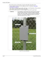
The AP cable includes 2 twisted pairs of black and white leads. The power leads are labeled 1/ONE and the data leads are labeled 2/TWO.
Connect the black power wire to -VDC and connect the white power wire to +VDC. Connect the black data wire to A side data and connect
the white data wire to B side data. Verify the labels on the twisted pair before making the connections.
ROC outputs
DRIC inputs
auxiliary inputs
-
+
OPT input 1
-
+
OPT input 2
OPT 4 NO
OPT 4 COM
OPT 4 NC
-
+
OPT input 3
-
+
OPT input 4
OPT 3 NO
OPT 3 COM
OPT 3 NC
OPT 2 NO
OPT 2 COM
OPT 2 NC
OPT 1 NO
OPT 1 COM
OPT 1 NC


