


Installing the LM100 gateway
Page 34
Senstar LM100 Product Guide
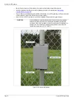
Grounding
The gateway requires a single ground reference. Connect the ground lug on the bottom of the
enclosure to an approved earth ground at the gateway’s location. Use a short, straight, heavy
gauge copper wire for the connection. Avoid sharp bends in the ground wire. The earth ground
connection must be stable and noise free. An improper or unstable earth ground can induce noise
in the gateway. Do not use the fence structure as an earth ground.
Input/Output ports
The LM100 gateway includes ten I/O ports that can be configured as either dry contact inputs or
relay outputs in any combination. The I/O ports are accessed through removable screw terminal
blocks. Each relay has an associated bi-color LED, which indicates the configuration of the relay’s
contacts. For relays set to Form A (normally open) the LED is green. For relays set to Form B
(normally closed) the LED is red. When a relay changes state, the LED changes color (green to
red, or red to green). The optional dry contact input card provides four additional inputs and the
optional relay output card provides four additional relays to supplement the I/O on the gateway.
I/O port jumpers
Each I/O port includes a pair of configuration jumpers which are set according to the intended use
of the port. For ports that will be configured as outputs and will source power to an external device,
and for all inputs, install the shunts on the headers. For ports that will be configured as outputs but
will not source power (dry contact outputs) park the shunts on a single pin (see
Outputs
The gateway’s outputs can source up to 100 mA at the same voltage as the gateway’s input power
in the high side drive configuration. The gateway’s capability to source power depends on the
capacity of the connected power supply. The outputs can also be configured as Form A or Form B
dry contact outputs (no power).
illustrates the gateway’s selectable output schematics.
Note
Consult the local electrical code for grounding information.
Note
The gateway can use either an input card or an output card, not both.
Figure 35: Gateway I/O port jumper settings
voltage sourcing outputs
dry contact outputs
and dry contact inputs
INPUT/OUTPUT
DRY CONTACT


