


Installing LM100 luminaires
Senstar LM100 Product Guide
Page 29
9.
Repeat this procedure for the power cables’ positive conductors and the red lead from the
luminaire.
10. If possible, temporarily apply power to test and verify the connection (the luminaire LEDs go
ON steady when power is first applied).
11. Push the 2 crimps up into the shaft of the luminaire, ensure that both of the power cables have
drip loops and screw the cable gland into the bottom of the shaft.
12. Using a 24 mm wrench, tighten the cable gland, and then tighten the compression nut on the
cable gland.
13. Attach the power cables neatly to the fence with UV resistant cable ties (P/N GH0916 - 1000
pieces) and continue making the power connections.
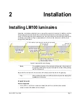
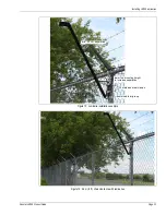
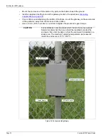
Installing the luminaire AP
The luminaire AP is usually attached to the same post as the gateway device. Mount the luminaire
AP in the same manner as the standard luminaires. The luminaire AP includes a 3 m (10 ft.) power
and data cable which is connected to the gateway device.
shows an installed luminaire
AP and the AP connections to the gateway. See
for
additional installation and connection details.
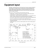
Figure 27: Crimping the splice
Figure 28: Power connection crimp tools
Figure 29: Luminaire AP mounting and connection
first crimp
second crimp (if necessary) in-line crimps fully cover the crimp ring
data cable shield
RS-485
A B
DC power
_ +
luminaire AP


