145
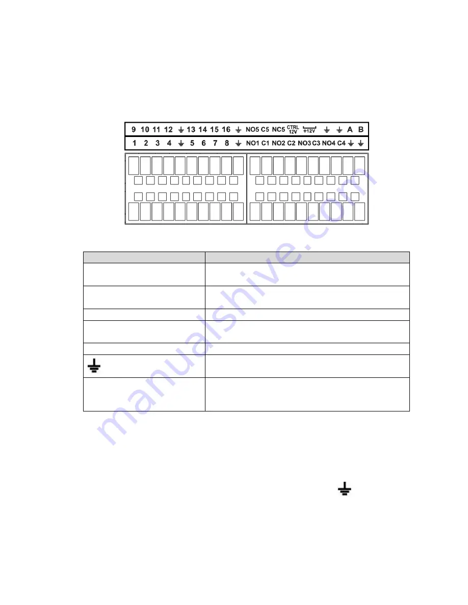
Figure 2-81
Icon
Function
1
~
16
ALARM1
~
ALARM16. The alarm becomes activated in the
low level.
NO1 C1
,
NO2 C2
,
NO3 C3
,
NO4
C4
Four NO activation output groups. (On-off button).
NO5 C5 NC5
One NO/NC activation output group. (On-off button).
CTRL 12V
Control power output. Disable power output when alarm is
canceled. Current is 500mA.
+
12V
Rated current output. Current is 500mA.
GND
A/B
485 communication port. They are used to control devices
such as PTZ. Please parallel connect 120T
Ω between A/B
cables if there are too many PTZ decoders.
Note
Different models support different alarm input ports. Please refer to the specifications sheet for
detailed information.
Slight difference may be found on the alarm port layout.
2.3.2
Alarm input port
Connect the positive end (+) of the alarm input device to the alarm input port (ALARM IN 1
~
16) of the
NVR. Connect the negative end (-) of the alarm input device to the ground end (
) of the NVR.
2.3 Alarm Connection
2.3.1
Alarm Port
The alarm port is shown as below. See Figure 2-81. The following figure is based on the professional 2U
series.
Содержание NVR-ELE4ME-WS
Страница 1: ...1080p Resolution 1yr Warranty Motion Activated Recording PTZ Control View From Anywhere NVR ELE4ME WS...
Страница 33: ...163 Figure 3 3 3 5 4 Compact 1U Series Please refer to Figure 3 4 for connection sample...
Страница 34: ...164 Figure 3 4 3 5 5 Compact 1U Wireless Series Please refer to Figure 3 5 for connection sample...
Страница 43: ...173 Figure 3 16 3 5 17 Professional 1 5U Series Please refer to Figure 3 17 for connection sample...
Страница 45: ...175 Figure 3 18 3 5 19 Professional 2U Series Please refer to Figure 3 19 for connection sample...
Страница 47: ...177 Figure 3 20 3 5 21 Professional 2U with RAID series Please refer to Figure 3 21 for connection sample...
Страница 48: ...178 Figure 3 21 3 5 22 Professional 3U Series Please refer to Figure 3 22 for connection sample...
Страница 50: ...180 Figure 3 23 3 5 24 Beneficio Vertical 1U Series Please refer to Figure 3 24 for connection sample...
Страница 51: ...181 Figure 3 24...
Страница 63: ...193 Figure 4 14 Figure 4 15 Step 2 Set network camera login password WARNING...
Страница 71: ...201 Figure 4 24 Step 2 Click device display edit interface See Figure 4 25...
Страница 148: ...278 Figure 4 114 Figure 4 115...
Страница 159: ...289 Figure 4 126 Figure 4 127...
Страница 161: ...291 Figure 4 129 Click draw button to draw the zone See Figure 4 130...
Страница 165: ...295 Figure 4 133 Click Draw button to draw a zone See Figure 4 134 Figure 4 134...
Страница 170: ...300 Figure 4 139 Click draw button to draw the zone See Figure 4 140...
Страница 183: ...313 Figure 4 151 Figure 4 152...
Страница 184: ...314 Figure 4 153 Figure 4 154...
Страница 214: ...344 Figure 4 189 In Figure 4 189 click one HDD item the S M A R T interface is shown as in Figure 4 190 Figure 4 190...
Страница 250: ...380 Figure 4 236...
Страница 294: ...424 Figure 5 60 Figure 5 61...
Страница 295: ...425 Figure 5 62 Figure 5 63...
Страница 319: ...449 Figure 5 97 Figure 5 98...
Страница 322: ...452 Figure 5 101 Figure 5 102...


