331
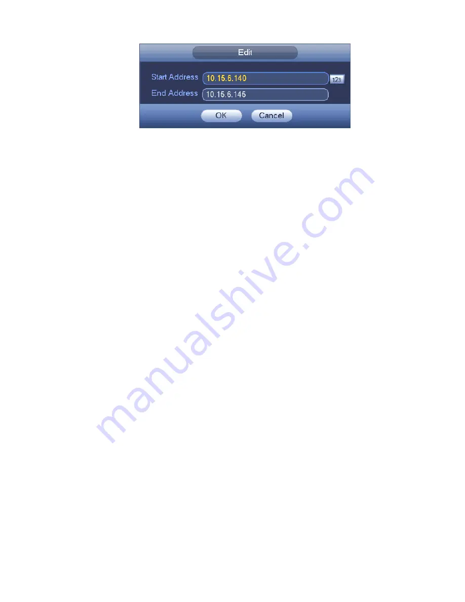
Figure 4-173
4.8.1.10 Email
The email interface is shown as below. See Figure 4-174.
SMTP server: Please input your email SMTP server IP here.
Port: Please input corresponding port value here.
User name: Please input the user name to login the sender email box.
Password: Please input the corresponding password here.
Sender: Please input sender email box here.
Title: Please input email subject here. System support English character and Arabic number. Max
32-digit.
Receiver: Please input receiver email address here. System max supports 3 email boxes. System
automatically filters same addresses if you input one receiver repeatedly.
SSL enable: System supports SSL encryption box.
Interval: The send interval ranges from 0 to 3600 seconds. 0 means there is no interval.
Health email enable: Please check the box here to enable this function. This function allows the
system to send out the test email to check the connection is OK or not.
Interval: Please check the above box to enable this function and then set the corresponding interval.
System can send out the email regularly as you set here. Click the Test button, you can see the
corresponding dialogue box to see the email connection is OK or not.
Please note system will not send out the email immediately when the alarm occurs. When the alarm,
motion detection or the abnormity event activates the email, system sends out the email according to the
interval you specified here. This function is very useful when there are too many emails activated by the
abnormity events, which may result in heavy load for the email server.
Содержание NVR-ELE4ME-WS
Страница 1: ...1080p Resolution 1yr Warranty Motion Activated Recording PTZ Control View From Anywhere NVR ELE4ME WS...
Страница 33: ...163 Figure 3 3 3 5 4 Compact 1U Series Please refer to Figure 3 4 for connection sample...
Страница 34: ...164 Figure 3 4 3 5 5 Compact 1U Wireless Series Please refer to Figure 3 5 for connection sample...
Страница 43: ...173 Figure 3 16 3 5 17 Professional 1 5U Series Please refer to Figure 3 17 for connection sample...
Страница 45: ...175 Figure 3 18 3 5 19 Professional 2U Series Please refer to Figure 3 19 for connection sample...
Страница 47: ...177 Figure 3 20 3 5 21 Professional 2U with RAID series Please refer to Figure 3 21 for connection sample...
Страница 48: ...178 Figure 3 21 3 5 22 Professional 3U Series Please refer to Figure 3 22 for connection sample...
Страница 50: ...180 Figure 3 23 3 5 24 Beneficio Vertical 1U Series Please refer to Figure 3 24 for connection sample...
Страница 51: ...181 Figure 3 24...
Страница 63: ...193 Figure 4 14 Figure 4 15 Step 2 Set network camera login password WARNING...
Страница 71: ...201 Figure 4 24 Step 2 Click device display edit interface See Figure 4 25...
Страница 148: ...278 Figure 4 114 Figure 4 115...
Страница 159: ...289 Figure 4 126 Figure 4 127...
Страница 161: ...291 Figure 4 129 Click draw button to draw the zone See Figure 4 130...
Страница 165: ...295 Figure 4 133 Click Draw button to draw a zone See Figure 4 134 Figure 4 134...
Страница 170: ...300 Figure 4 139 Click draw button to draw the zone See Figure 4 140...
Страница 183: ...313 Figure 4 151 Figure 4 152...
Страница 184: ...314 Figure 4 153 Figure 4 154...
Страница 214: ...344 Figure 4 189 In Figure 4 189 click one HDD item the S M A R T interface is shown as in Figure 4 190 Figure 4 190...
Страница 250: ...380 Figure 4 236...
Страница 294: ...424 Figure 5 60 Figure 5 61...
Страница 295: ...425 Figure 5 62 Figure 5 63...
Страница 319: ...449 Figure 5 97 Figure 5 98...
Страница 322: ...452 Figure 5 101 Figure 5 102...


